HOME AUTOMATION, INC. Model 87A00-1 Camera Server Installation and User Guide Document Number 87I00-1 Rev.
DISCLAIMER • While every effort has been made to ensure that the information contained in this guide is accurate and complete, no liability can be accepted for any errors or omissions. • HAI reserves the right to change the specifications of the hardware and software described herein at any time without prior notice.
FCC NOTICE This device complies with Part 15 of the FCC Rules. conditions; Operation is subject to the following two 1. This device may not cause harmful interference, and 2. This device must accept any interference received, including interference that may cause undesired operation. Note: This equipment has been tested and found to comply with the limits for Class B digital devices, pursuant to Part 15 of the FCC rules.
Table of Contents 1. Introduction ·········································································································································1 1.1. Model 87A00-1 Camera Server··································································································1 1.1.1. About the Camera Server ·································································································1 1.1.2.
5.5. Record Setup ···························································································································37 5.5.1. Recording on USB Flash Drive························································································37 5.5.2. Recording on FTP server·································································································40 5.5.3.
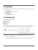
1. Introduction 1.1. Model 87A00-1 Camera Server The 87A00-1 Camera Server is a device that transmits video and audio data via network in real-time. The server converts the analog video signals and audio signals into digital data and compresses them for on-line transmission. Cameras can then be viewed at home or over the Internet on a PC, OmniTouch 5.
1.2. Package Contents Before installing the Camera Server, please make sure that the following items are included in the box: 1. 2. 3. 4. 5. 6. Camera Server 12VDC Power Adapter with Power Cord 2 Terminal Block 2 Audio Cables Mounting Hardware Software Utility and Manual CD 1.3. Factory Default Settings Factory default settings are as follows: IP address: 192.168.xx.yy Mask: 255.255.0.0 Gateway: 192.168.0.
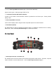
2. Operation 2.4. Front Panel ⑦ ⑥ ② ① ③ ⑤ ④ ① Status LED ② Network LED Status (Orange) and Network (Green) LED indicators display the following system information: Status (Orange) Network (Green) Power Off Off Off Booting in progress On Off Successful Network Connection On Blinking Failed Network Connection On Off Blinking (Slow) Blinking (Fast) Data Transmission in Progress 1.
③ and ④ Video Input BNC Connectors (Vin 1, Vin 2, Vin 3 and Vin 4) Used for video inputs. Video input type: NTSC or PAL ⑤ Termination Resistor DIP Switch (75Ω ON) A switch to turn On/Off a 75Ω termination resistor is provided for each video input. Factory default setting is ON. ⑥ Video Output BNC Connector Vout is used to display quad or single channel composite output to an external monitor.
Audio Input Connector ② Audio Output Jack (Aout) The Camera Server has one mono audio output using the stereo socket. Even if a stereo speaker is connected, both sides will have the same sound (mono output). The Camera Server audio output is very low-wattage, therefore it requires amplified speakers (do not use headphone/earphone directly).
③ Digital Input (DI 1-4) The Camera Server has 4 Digital Inputs as shown. Each input can be connected either a voltage type sensor or relay type sensor (dry contact). Do not use voltage and relay type sensors together.
④ Digital Output (DO 1-4) The Camera Server has 4 12VDC Digital Outputs. The Digital Outputs can be connected as shown: Digital Output Connections ⑤ RS-232C Terminal Blocks (RS-232C) The RS-232C Terminal Blocks are used to connect an RS-232 serial device. The RS-232C serial port consists of Transmit (Tx), Receive (Rx), and GND.
⑥ RS-485 Terminal Blocks (RS-485) The RS-485 Terminal Blocks are used to connect RS-485 serial devices such as PTZ cameras. The RS-485 serial port consists of DATA+, DATA-, and GND. RS-485 Connection ⑦ LAN Connector (Ethernet) This is a RJ45 LAN connector for 10/100 Base-T Ethernet. ⑧ Power Adaptor Connector (DC 12V) Power connector input for the 12VDC, 3A power supply. ⑨ USB Port This USB port is used for recording images to a USB storage device such as a USB flash drive.
3. Web Interface 3.1. Accessing the Web Interface To access the web interface of the HAI Camera Server, open Internet Explorer and enter the IP address of the 87A00-1 into the address bar. Enter the IP address in the address bar of the browser as shown below: http://(IP address) For example: http://192.168.1.2 User Login The 87A00-1 user’s log in page will be displayed.
When initially accessing the 87A00-1 web interface, the client viewer software is automatically downloaded and installed. The first time you access the web interface, the Active-X Control Plug-In must be installed. If the Active-X Control is not currently installed or if you are accessing the web interface for the first, following prompt will appear. NOTE: The 87A00-1 browser interface requires the Active-X Control Plug-In for Internet Explorer.
3.2. ActiveX Installation You will need to install ActiveX for displaying images. Click “Pop-up Blocked” and then “Install Active X Control” as shown below. At the Security Warning, click the “Install” button.
4. Main Page Configuration 4.1. Single View When the installation of the client program is complete and your login is accepted, the 87A00-1 Viewer is automatically connected and begins displaying video. SingleView shows only one camera on a page. Video 1 is set as the default channel and other channels are chosen from the drop-down combo box. 12 • PLAY: Play the current camera. • STOP: Stop the current camera.
• SNAPSHOT: Save a snapshot of current video image. Note: The file is saved in \My Documents\Snapshot folder • Full Screen: Stretches the camera image to fill the full screen. • PTZ: Virtual PTZ control keyboard is displayed. This is used to control PTZ cameras. • Motion View: When motion detection is set on the Event menu, you can see the detection status on the current image screen.
4.2. Multi View MultiView displays all 4 cameras on one page. Individual Play, Stop, and Snapshot button are available for each camera in MultiView mode. 4.3. Setup Setup allows users to completely configure the Camera Server. See 5. Setup Configuration for an explanation of each option and how to set and change the values.
5. Setup Configuration The Setup Configuration pages allow you to completely configure the Camera Server. Click Setup on the main page of web interface.
5.1. Video Setup 5.1.1. Video Settings Select Video Settings from the Video menu to select the Video Type, Codec, Resolution, FPS, Bitrate Mode, Bitrate, Quant, GOP size, Brightness, Contrast, Saturation, and Hue. i Note Whenever a camera is viewed on an OmniTouch 5.7e or OmniTouch 10p, the Resolution, FPS, Bitrate Mode, and Bitrate of the camera on the Camera Server will automatically change based on the settings of the camera in the OmniTouch touchscreen.
Resolution Select the desired resolution from the Resolution box. Refer to the table below. D1 VGA QVGA 4CIF 2CIF CIF QCIF NTSC 720x480 640x480 320x240 704x480 704x240 352x240 176x112 PAL 720x576 640x480 320x240 704x576 704x288 352x288 176x144 FPS (Frames per Second) Select the desired FPS from the FPS box. This value represents the number of encoded frames you want to get per 1 second. Video Format NTSC PAL Available frame rate 30, 15, 7.5, 10, 6, 3.75, 2, 1 25, 12.5, 8, 6.
GOP Size Select the desired GOP size from the GOP box. GOP is an abbreviation for “Group of Pictures”. The GOP number represents a frame interval. If the GOP size is 1, only I frame is generated in 1 second. If the GOP is set to 15, 15 frames are captured per 1 second. The GOP can be a number from 1 to 255. The default value is 15. Brightness/Saturation/Contrast/Hue The range of each value is 0 to 255. The default value for each is 128. 5.1.2.
String Enter the maximum length of OSD text (ASCII character string). X/Y Type the location of the string by entering the X and Y coordinates. For example, if the coordinates are (0, 0), the time stamp will be shown on the top left of image. Input range of coordinate value: X: 0 - 44 Y: 0 - 29 OSD Time configuration i Note The OSD time setting is available only on the 1st camera and the other cameras do not support the Time OSD setting. The OSD time is refreshed every 1 second.
5.1.3. Advanced Horizontal delay A higher setting moves the image towards the left. The setting ranges from 32 to -32 Vertical delay A higher setting moves the image towards the top. The setting ranges from 4 to -4 Copying an image to shared memory This setting allows the Camera Server make the best use of the source. De-interlace Mode Select Yes to enable de-interlacing. Select No to disable de-interlacing.
5.2. Audio Setup The Audio Setup page provides the options for the audio input and the audio output. 5.2.1. Audio Input Settings The Audio Input Configuration settings are required to listen to the sound from the location where the camera is installed. In order to test and use this feature, the microphone should be connected to the audio port of 87A00-1 Camera Server. Enable Enables or disables the audio input. Name Enter a nickname for the audio input. Stream Type Select an audio input format.
5.2.2. Audio Output Settings The Audio Output Configuration settings are required to talk to people at the location where the camera is installed. Configure the values and click the Save button. This feature enables your PC to send audio to the speakers on the Camera Server. In order to test and use this feature, the microphone should be connected to the audio port of your PC. Likewise, the speakers should be connected to the 87A00-1 Camera Server. Name Type a nickname for the audio output.
5.3. Network Setup The Network Setup page is used to configure various network and operational settings of the 87A00-1 Camera Server. 5.3.1. General Settings IP Address Configuration If the Network mode is set to DHCP, the IP address, Subnet mask, Gateway and DNS Server settings will be received from a DHCP server. If Network mode is set to Static, the IP address, Subnet mask, Gateway, and DNS Server settings must be manually configured.
5.3.2. QoS Settings The 87A00-1 Camera Server uses a DSCP model for implementing QoS. Additionally, video, audio, and event classes are available for that. What is DSCP? It is short for Differential Services Code Point, which is a field in the header of IP Packets for packet classification purposes. Video DSCP: DSCP of video packet Audio DSCP: DSCP of audio packet Event DSCP: DSCP of event packet DHCP values should be specified in a decimal number converted from original 6 bit binary digit.
5.3.3. Multicast Settings This page provides the multicast configuration of each channel. The addresses are a group of address which is required to receive data from the router. The values in the boxes are default. You can set the values according to your network requirement. The Camera Server supports only RTSP multicast (UDP/RTP Multicast is not supported).
5.3.4. DDNS Settings For DDNS configuration setup, you must first create a DDNS account with dyndns.com. Server Enable: Select YES to use DDNS. Server Type : DynDNS (no other settings allowed at this time). Address: www.dyndns.com (no other servers allowed at this time). User ID: your user ID created at the Dyndns.com. User PW: your password registered at the Dyndns.com (case-sensitive). DNS name: your dynamic domain host server name.
5.3.5. Advanced Settings RTSP Port This is the port number for first channel for RTSP. If a device has more than one channel, the port number of next channel succeeds the port number of the first channel. For example, if the port number of first channel is 554, the second channel would be 555. Web Port This is the port number for HTTP. User RTST Port This setting is required ONLY when you have set ‘port forwarding’ on router device.
5.4. Event Setup This manual assumes that Motion Detection is an event action trigger. So, consider this carefully and follow the setting step as the order below. If your event factor is not Motion Detection, you can just skip Step2: Motion setting. Step 1: Event Server setting Step 2: Motion setting Step 3: Event setting (related to the event setting and motion detection setting you configure) The event server supports SMTP, TCP, and FTP servers. Select Motion from the Event menu.
5.4.1.1. SMTP Server Settings To register the SMTP server, click on the SMTP in the box and press the Modify button on the right. FromEmail Enter the email address of a sender. MailServer1 Enter the SMTP server address. MailServer1 Port Enter the SMTP server port number (default port number 25). ID Enter the ID of the sender’s email account. Password Enter the password of the sender’s mail account (case-sensitive).
5.4.1.2. FTP Server Settings To register the FTP server, press the Add FTP button. Name Enter a descriptive name for the FTP server. Address Enter the IP address or domain name of FTP server NOTE: To use domain name of FTP server, make sure if the DNS setting is enabled. Port Enter the port number of FTP server (0 – 65535). User ID / User PW Enter the FTP Server log-in ID and Password (case-sensitive).
5.4.1.3. TCP Server Settings To add a TCP server, press Add TCP button. Name Enter a descriptive name for the TCP server. Address Enter the IP address of TCP server. Port Enter the port number of TCP server (0 – 65535).
5.4.2. Motion Detection Settings After all of the settings have been entered for the Event Server, select the Motion tab to enter the settings for the motion detection functions. How to register Motion Detection Step 1: Select a camera from the Image Source combo box and then press Play button. Step 2: Select a layer from the Layer ID combo box. Step 3: Check the Motion Enable checkbox. Step 3: Right-click anywhere on the camera display to make an Area rectangle.
5.4.3. Event Settings To register an Event, follow Steps 1-3 below. Step 1 1. Click Add to create an Event. Name Enter a descriptive name for the event Event Type • • Software – device boots, motion detection, video losses, etc. Hardware – Digital Input activation (such as sensor).
Software Mode Select one of the following event modes: Motion Detection, Video Loss, and Boot. Motion Detection: Event occurs when the motion is detected. Video Loss: Event occurs when there is loss of video (disconnected or connected). BOOT: Event occurs when the Camera Server is rebooted. MD Enable only if software mode is set to Motion Detection. To set the MD value, press the View CGI button on the Motion setting page to see the MD values.
Step 2 1. Click on the Event tab on the left menu and then select the event that you created in the box. 2. Click the Modify button. 3. Click the Action button. Step 3 1. Select the proper server from the Server list and set the respective values. Event Action The actions that are created are listed. Select an Event Action from the list. Server Select the appropriate server from the list. TCP, SMTP, FTP, DO and USB recording server are available.
Message Enter an email message that will be sent. EmailTo Enter an email address of the recipient. Subject Enter the subject of the email. ImagePerMail Enter “1” to send a captured image with the email message. Otherwise, enter “0” for no image. When you set the values on the Event Action Configuration page, depending on the Server, the required values may be different.
5.5. Record Setup 5.5.1. Recording on USB Flash Drive Before removing the USB flash drive from the Camera Server after recording…change the USB Mount value to No first. Otherwise, the recording may not work properly. Caution ! Preparation before recording Step 1: Insert the USB flash drive into the USB port on the Camera Server. Step 2: Click Record from the Record menu and set the value of USB Mount to YES as above. Step 3: Select USB for the value of Record Device.
How to record video NOW (Passive mode) Step 1: Set the Record Enable as YES Step 2: Set the Record Mode as Passive Step 3: Enter the Port Number and Record Recycle • Port number: Used for playback. 2100 is set as the default. • Record Recycle: Rotate lets the new files overwrite existing files when USB memory is full. None lets the recording stop if the USB memory is full. Step 4: PostTime is set in seconds. If you want to record for 30 minutes, type 1800 for the value of PostTime.
How to record on SCHEDULE (Schedule mode) If you want to record the video according to the specific date and time, follow the instructions below. Step 1: Follow the same steps of How to record Video NOW except for Step 2. Step 2: Set the Record Mode to Schedule. Step 3: Set Record Weekdays, Start Time and End Time as described below: • Record Weekdays Assign days for recording. The first digit corresponds to Sunday and last digit corresponds to Saturday.
5.5.2. Recording on FTP server Step 1: In order to record the video on an FTP server, the FTP server must be added in advance. Refer to section 5.4.1.2 FTP Server Settings. Step 2: Set Record Device as FTP. Step 3: Set Record Mode as desired. Refer to section 4.5.1 Recording on USB flash drive. Step 4: Set the FTP Server Number. This is available only after Step 1 has been completed. Step 5: PostTime is set in seconds. If you want to record for 30 minutes, type 1800 for the value of PostTime.
5.5.3. Playback the recoded data on the USB device If the USB recording steps have been completed, the recording status can be viewed on the USB Record List page.
5.6. System Setup 5.6.1. System Date Device Time Displays the date and time of Caners Server Time Zone Select your time zone Time Mode You can select a time mode with 3 options. 42 • Client Time: Synchronized with your current PC time. • NTP Server: Synchronized with a NTP server. By default ‘time.nist.gov’ is the selected server; however any NTP server can be selected from the list or one can be manually entered. • User Setting: The time and date will be manually entered.
5.6.2. System Update This page is used to update of the software in the Camera Server and to display the current version for various software modules. System Update You can upload firmware files and update your Camera Server. Click the Search button and choose the file you want to upload. Then click the Upgrade button.
5.6.3. User Management User Management is used to add user login accounts to the Camera Server. There are two user types provided by default: User root guest Password pass guest Security Level Admin Guest Accounts can be created up to 10 including two default users. • ID: Up to 32 characters with the combination of alphabets and digits. First character must be an alphabet (case-sensitive). • Password: From 3 to 8 characters with the combination of alphabets and digits (case-sensitive).
How to modify a user 1. Select a user to modify from the User List 2. Click Modify. 2. Modify the password or security level. 3. Select Modify on the “User Modify” dialog. 4. Click Close on the “User Modify” dialog. 5.6.4. PTZ Protocol This page shows the list of current PTZ protocols built-in the Camera Server and also allows you to upload a new PTZ protocol. How to add PTZ protocol manually 1. Click the Browse button. 2. Choose the required file and click the Upload button. 3.
5.6.5. System Information This page shows the system information as described below: 87A00-1 Information • • • MAC: MAC Address TIME: Date and time information on the Camera Server Version Information • • • • 46 Bootloader: Bootloader version.
5.6.6. Reboot The Camera Server can be rebooted from the web interface without physically touching the device. Click the OK button. As confirmation dialog is displayed. Select OK to reboot the Camera Server. It will take about 1-2 minutes to complete the rebooting process.
5.7. IO Setup 5.7.1. Serial Port Setting This page provides the configuration of RS-232C and RS485.
5.7.2. DI/DO Setting This page is used to see the status of the Digital Inputs (DI) and Digital Outputs (DO) on the Camera Server. It also allows you to control the state of the Digital Outputs. This page is refreshed every 3 seconds to update the status of each Digital Input and Digital Output.
5.7.3. PTZ This page allows you to select the PTZ Protocol for each camera. PTZ protocol options are shown in the drop down combo box. You can choose a protocol for each camera. 1. Check Enable in the check box and choose the desired protocol. 2. Set the Addr and CommPort foe each camera input. 3. Click the Apply button. PtzDriver Select the desired protocol from the list. Addr Set the Addr value according to the ID set by dip switch on the PTZ camera.
5.7.4. External Video out Setting This page provides the external video output settings and video loopback function settings. Video Out You can choose either single view or multi-view for the stream on the external output. Quad displays 4 channels as a quad multi-view on the external video out. Video Loopback Video Loopback is not currently implemented on the 87A00-1 Camera Server.
6. Resetting the Camera Server 6.1. Rebooting The camera server can be rebooted as follows: 1. Press the Reset button for 1 second. ¾ The Status LED and Network LED will blink together, twice. Stop pressing the Reset button. 2. When the reset function has been completed, The Status LED and Network LED will stop blinking. 6.2. Reset to Factory Default The camera server can be initialized to factory default settings as follows: 1.