HOME AUTOMATION, INC. Control & Security System Installation Manual Document Number 20I00-1 Rev. 2.
Home Automation, Inc. Installation Manual Document Number 20I00-1 Rev. 2.4 May, 2003 Copyright ! 1999-2003 Home Automation, Inc.
CONTENTS INTRODUCTION........................................................................................................................................... 1 PLANNING .......................................................................................................................................................................................1 INSTALLATION............................................................................................................................................
INSTALLER SETUP.................................................................................................................................... 31 SETUP CONTROL ........................................................................................................................................................................31 X-10 HOUSE CODE ................................................................................................................................................................
OMNI II SPECIFICATIONS ...................................................................................................................... 51 UNDERWRITER'S LABORATORIES (UL) INSTALLATION REQUIREMENTS .......................... 52 24-HOUR STANDBY BATTERY CAPACITY......................................................................................... 53 SMOKE DETECTOR INSTALLATION GUIDELINES ........................................................................
INTRODUCTION This installation guide is intended as an aid to installing the Omni II Control & Security System. The installer should also have thoroughly reviewed and understood the Omni II Owner's Manual, which has important information regarding final setup of the system. This manual assumes that the installer has a basic understanding of installing a security system. This guide applies to the 20A00-1, -4, and -12 versions of the Omni II series controller.
INSTALLATION Go over your plan with your customer. 1. Install the entire system. Refer to sections in this manual to see how to install various components. 2. Follow the Power-Up and Checkout procedures. 3. Explain the basics to the customer. Deliver all manuals and documentation. 4. Follow up with your customer to keep them satisfied. CONTROLLER HOOKUP 1. When choosing a place to mount the controller, consider the following: a.
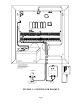
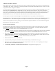
1/4" SPACING BLACK WIRE TO RED WIRE TO + YUASA NP7-12 OR EQUIVALENT BATTERY 12V 7AH THE BATTERY IS NON-POWER LIMITED. THE BATTERY LEADS MUST BE SEPERATED FROM ALL OTHER POWER LIMITED/CLASS II WIRING IN THE ENCLOSURE BY AT LEAST 1/4" COLD WATER PIPE OR GROUND ROD TWO - WAY POWER LINE INTERFACE 24 VAC 40 VA 4 CONDUCTOR 14 GA. WIRE POWER TRANSFORMER REVERE MODEL RT-2440SL OR EQUIVALENT GOUNDING METHOD MUST BE IN ACCORDANCE WITH THE NATIONAL ELECTRIC CODE, ANSI/NFPA 70.
ABOUT SECURITY ZONES Each of the 48 security zone inputs on an Omni II system may be configured as a burglary zone, a fire zone, a temperature zone, or an auxiliary input. Zones 1-4, however, are the only inputs that can be used with 2-wire smoke detectors. Zones 9-16 are the only inputs that can be configured as a PESM. An external 1000-ohm end-of-line zone resistor is required for all zones unless the Setup item ZONE RESISTERS is set to "No".
ZONE ZONE ZONE (NO) OUT (NO) SWITCH 12V (OUTPUT) WARNING (NC) (NC) 1K EOL 1K EOL 1K EOL BURGLARY ZONES SMK SMK JP11-14 JP11-14 COM TO PREVENT RISK FROM ELECTRIC SHOCK, DE-ENERGIZE THIS UNIT AND DISCONNECT TELEPHONE LINES BEFORE SERVICING. NRM 12V 12V 4-WIRE SMOKE ZN NRM SWITCH 12V (OUTPUT) OUTPUT ZN 1K EOL INPUT ZN ZONE (1-4) 1K EOL ZONE (1-4) IN 4-WIRE FIRE ZONE 12V 2-WIRE SMOKE 2-WIRE FIRE ZONE NOTES: 1.
ABOUT FIRE ZONES The Omni II system supports normally open (closed for alarm), two-wire or four-wire smoke detectors. Two-wire smoke detectors can only be connected to Zones 1-4. Four-wire smoke detectors can be connected to any zone. An external 1000-ohm end-of-line resistor must be used for all fire (and gas) zones. When Zones 1-4 are configured as a Supervised Fire (two-wire or four-wire) or Gas zone, the corresponding Zone Jumpers (JP11-JP14) must be in the "SMK" (smoke) position.
WHEN Z1-Z4 IS CONFIGURED AS A SUPERVISED FIRE OR GAS ZONE, THE CORRESPONDING ZONE JUMPERS J11-J14 MUST BE IN "SMK" POSISTION SYSTEM SENSOR MODEL 2100TS BOTTOM PLATE ZONE ZONE SYSTEM SENSOR MODEL 2100TS BOTTOM PLATE ZONE ZONE MODEL 1503A0011 1K OHM EOL RESISTOR FIGURE 3 - TWO-WIRE FIRE ZONE CONNECTIONS Page 7
WHEN Z1-Z4 IS CONFIGURED AS A SUPERVISED FIRE OR GAS ZONE, THE CORRESPONDING ZONE JUMPERS J11-J14 MUST BE IN "SMK" POSISTION GREEN YELLOW BLACK RED SYSTEM SENSOR MODEL 2112/24TR ZONE YELLOW ZONE GREEN +12V RED GND BLACK BLACK RED YELLOW GREEN SYSTEM SENSOR MODEL 2112/24TR BOTTOM PLATE ZONE YELLOW ZONE GREEN +12V RED GND BLACK SYSTEM SENSOR MODEL 2112/24TR SYSTEM SENSOR MODEL 2112/24TR BOTTOM PLATE BOTTOM PLATE BOTTOM PLATE ZONE YELLOW GREEN ZONE YELLOW ZONE ZONE GREEN +12V
TELEPHONE CONNECTIONS 1. If an RJ31X jack has been supplied by the telephone company, it is probably wired correctly and the controller can be connected by plugging the supplied 8 conductor telephone cable into the RJ31X jack. The other end of the cable is spaded. The green, red, brown, and gray wires must be connected to the controller at the designated terminals under the section of the board marked 'PHONE'. 2. If required, install the supplied RJ31X jack as shown in the following diagram.
RED(-) GREEN(+) TELEPHONE NETWORK INTERFACE RED(-) GREEN(+) CUSTOMER ACCESS SURGE ARRESTOR SURGE ARRESTOR MUST BE GROUNDED! RJ11 HOUSE PHONE JACK(S) TO ALL HOUSE TELEPHONES, PBX, AND COMPUTERS TO TELCO INTERFACE AT SURGE ARRESTOR FIGURE 5 - RJ31X JACK CONNECTIONS Page 10 GRAY BROWN RED GREEN BEND TAB UP IF NECESSARY TO ENSURE TIGHT FIT
LCD CONSOLE HOOKUP 1. 8 LCD Consoles (Models 11A00-1, 11A00-2, 11A00-9, and 15A00) MAXIMUM per system, subject to power availability. 2. Use 4-conductor 22-gage wire, 1000 feet maximum length. Consoles can be homerun or daisy chained. This length shall be divided by the total number of consoles at the end of the run. For example, for 8 consoles, the maximum length reduces to 125 feet. All LCD Consoles are connected to the same 4 wires, +12, GND, A, B. 3.
LANGUAGE This option is to display the 'console setup' text on the LCD display in English, French, Italian, or Spanish. Select one of the languages, then press the # key. EXIT SETUP MODE To exit Setup Mode, press and hold the 4 and up arrow (!) keys simultaneously for about 1 second. The console will return to normal operation. You may need to press (*) to restore the display. CONSOLE SELF TEST Use the self test mode to verify the proper operation of the console. 1.
GREEN YELLOW RED BLACK FOR MODEL NUMBERS SEE NOTE 1 UNDER "LCD CONSOLE HOOKUP" CONSOLE FACE (SNAPS ON TO BOTTOM PLATE) BOTTOM PLATE CONSOLE PC BOARD (MOUNTED TO CONSOLE FACE) YELLOW GREEN RED BLACK CONNECT ENDS OF SUPPLIED CABLE TO CORRESPONDING ENDS OF 4 - WIRE CABLE FROM CONTROLLER FIGURE 6 - CONSOLE CONNECTIONS Page 13 SUPPLIED CABLE (PLUGS INTO J1)
SOUNDER OUTPUTS The Horn Output provides 12VDC to power bells, piezo sirens, self-contained sirens, and siren drivers (do not connect speakers to the Horn Output). Sounders can draw up to 1 amp MAXIMUM, split between the Interior and Exterior Horn Outputs - (See Specifications for UL Ratings). Use a relay connected to an auxiliary power supply if higher current draw is required. INTERIOR SOUNDER HOOKUP 1. Locate the interior sounder in a central location. The sounder is very loud.
RED BLACK RED FIGURE 7 - SOUNDER CONNECTIONS Page 15
CONTROLLER OUTPUTS The Omni II provides 8 programmable hardwired voltage outputs and two horn voltage outputs.
COMMUNICATOR OUTPUTS This output can be used for radio communications or any other type of auxiliary communications to augment the built-in digital and voice dialers. Any communications device can be used with the Omni II, provided that it is powered by 12 VDC, has 12 VDC triggered inputs, and has 2 (or more) channels. The 'Communicator' outputs are activated 3 seconds before the Omni II dialer begins to dial either using its built-in digital dialer or voice dialer.
GREEN YELLOW RED 1KEOLRESISTOR BLACK YELLOW GREEN RED + GREEN + BLACK RED MOMENTARY CONTACT KEYSWITCH FIGURE 9 - REMOTE KEYSWITCH CONNECTIONS Page 18
HAI THERMOSTATS Omni II supports up to 4 HAI RC-Series Communicating Thermostats. The controller can send commands to the thermostat to change mode, cool setting, heat setting, status of fan and hold, and other items. FIGURE 10 - HAI THERMOSTAT CONNECTIONS Page 19 YELLOW GREEN BLACK Run a 3 (or 4) conductor wire from Omni II to the thermostat location. All thermostats are connected in parallel to Zone 16 and Output 8. Connect the red COMM cable wire with the black COMM cable wire.
PROGRAMMABLE ENERGY SAVER MODULES NOTE: Programmable Energy Saver Modules must be connected to zones 9-16 on the Omni II controller. 1. Omni II can support up to 8 Programmable Energy Saver Modules (PESM). Each PESM requires one security zone input and one controller output. The zone input corresponds to the controller output (Zone 9 and Output 1 through Zone 16 and Output 8, respectively). If Zone 9 is used, Output 1 must be used as its pair. 2.
4. Heat Pumps Programmable Energy Saver Modules are compatible with heat pumps, however, the savings gained by setting the heat pump back may be erased by the auxiliary heaters when the heat pump tries to recover from the setback. A PESM will work best with heat pumps that have one or more of the following features: a. An outdoor temperature switch that prevents the auxiliary heat from coming on unless it is very cold outside. This is sometimes called a "heat balance" switch. b.
BLACK RED YELLOW GREEN EXISTING LOW VOLTAGE THERMOSTAT RED LED ON - ENERGY SAVER IS OVERRIDING THERMOSTAT BLACK YELLOW RED GREEN OFF - THERMOSTAT IS WORKING NORMALLY HEAT / AIR SYSTEM PROGRAMMABLE ENERGY SAVER MODULE FIGURE 12 - PESM CONNECTIONS Page 22
BUILT-IN SERIAL PORT Omni II has a serial port (J1) built onto the controller (labeled SERIAL 1). The interface is a modular connector located in the upper left corner of the controller. It uses either the Omni-Link or Pro-Link Protocol for connections to the Internet via HAI Web-Link II, personal computers, and other optional interfaces like touchscreens, voice recognition, lighting controls, and home theater controls. The serial interface supports both RS-232 and RS-485 connections.
4 POSITION MODULAR PHONE CABLE 7 RTS DB9-FEMALE BOTTOM VIEW - YELLOW WIRE ON TOP - 8 CTS 3 TX 6 7 8 9 YELLOW GREEN RED BLACK 2 RX 1 2 3 4 5 - TAB UP - 1 DCD 5 GND TOP 4 DTR 6 DSR SIDE FIGURE 13 - RS-232 CONNECTIONS 4 POSITION MODULAR PHONE CABLE - YELLOW WIRE ON TOP - A B - TAB UP - YELLOW GREEN TOP SIDE FIGURE 14 - RS-485 CONNECTIONS Page 24
SYSTEM POWER UP PROCEDURE 1. Carefully review hookups to the zones, grounds, sounders, and consoles. 2. Disconnect 1 lead of both the interior and exterior sounders. NOTE: Follow this power up procedure to verify proper operation of the power supply, battery charger, and low voltage cut out relay. 3. The positive lead to the battery should be disconnected at this time. Make sure that the red battery wire is not touching anything. 4. Plug in the power transformer. - The AC ON LED should illuminate.
5. Record the owner's NAME and ADDRESS in the ADDRESS speech memory as shown in SETUP ADDRESS in the OWNER'S MANUAL (Press 8, 9, then 1111 or the current Master code to record the address). NOTE: DO NOT record any TOUCH TONES in the ADDRESS!! 6. Check that all in-house phones are working. BURGLAR ZONE CHECK OUT 1. With all doors and windows closed and all motion detectors and security devices secure, the console display should read "SYSTEM OK". 2. If any zones are abnormal, check your wiring.
CUSTOMER CHECKOUT After you have completed the system check out and everything works, be sure that the customer knows how to: 1. Disarm/silence the system (OFF, 1111 or current User code). HAVE THE CUSTOMER PRACTICE! 2. Change the codes. 3. Get the menu over the in-house phones. You should also: 4. Demonstrate arming and disarming. 5. Demonstrate home control. 6. Demonstrate setup and programming. 7. Show him/her how to program the dial out numbers. 8. Deliver the Owner's Manual. 9.
Follow this procedure for removing the controller board: 1. If possible, upload the programs and configuration. (This will not be possible if the status LED isn't flashing or if you can't get the voice to work.) 2. Unplug the power transformer. 3. Disconnect the battery 4. Disconnect the RJ31X modular cable at the jack!! If you only disconnect it at the Omni II controller only, the house phones won't work. 5. Disconnect the X-10 cable. Disconnect the serial cable. 6.
DIGITAL COMMUNICATOR The Omni II digital communicator can use Contact ID, or Standard 4/2 or 3/1, (20 pps, 1800 Hz data, 2300 Hz handshake), or (10 pps, 1900 Hz data, 1400 Hz handshake), dual round compared format. Any central station with modern equipment can receive these formats. Compatible receivers are Ademco, Radionics, Osborne-Hoffman, Linear, FBI, and Silent Knight. It is up to the installer to verify compatibility.
3/1 FORMAT Older central stations may require a 3/1 format. To use 3/1 format, both account numbers must be changed to 3 digit codes and EVERY alarm code must be changed to a 1-digit code. Do not mix code lengths! OPENING AND CLOSING REPORTS The Omni II system can send opening and closing reports by user to the central station. When the system is disarmed by user code 1-16, the communicator can call the central station and report that the system was disarmed (opened) with the user code that was used.
INSTALLER SETUP This section describes the items that the installer must setup as part of system installation. The Installer Setup mode is used to configure the general operation of the system, the Outputs, the Areas, the Zone Types, the Digital Communicator, and various other settings. This information is covered only in this manual. All other SETUP items, including delay times, names and voices, voice dialer, and codes are covered in the Owner's Manual, Document No. 20R00-1.
OUTPUT TYPES An output type must be specified for each of the voltage outputs and for the interior and exterior horn outputs.
OUTPUT 7 TYPE: 0 GENERAL PURPOSE #=CHNG ↕ OUTPUT 8 TYPE: 0 GENERAL PURPOSE #=CHNG ↕ INTERIOR HORN: INT SNDR 4 #=CHNG ↕ EXTERIOR HORN: EXT SNDR 7 #=CHNG ↑ For output types, the current setting is shown on the bottom line. Press the ' # ' key to select a new type from a list of types. The display shows: SELECT TYPE: INT SNDR 6 ↕ Use the Up and Down arrow keys to scroll through the list, or select the appropriate output type number. Then press ' # ' to enter the new type.
Z 1 TYPE THROUGH Z 48 TYPE This item specifies the zone type for each zone. All choices are listed in this manual under DESCRIPTION OF ZONE TYPES. For zone types, the current setting is shown on the bottom line. ZONE 1 TYPE: AUXILIARY 64 #=CHNG ↕ ZONE 48 TYPE: AUXILIARY 64 #=CHNG ↑ THROUGH To change a zone type, press the ' # ' key, then use the arrow keys to scroll through the list of zone types. Press the ' # ' key to select a new type.
LATCHING ZONE TYPES When any device (other then FIRE or GAS) is connected to SWITCH 12V or a Switched Power Output, the zone must be configured as one of the LATCHING ZONE TYPES (latching perimeter, latching night interior, latching away interior, and latching tamper). LATCHING ZONE TYPES ignore the status of that zone during power cycles. Used primarily when the FIRE ALARM VERIFICATION feature is being used or if more than one area is being protected. This type will ignore the status of LATCHING ZONES (i.
TAMPER ZONES should be used for items such as gun cabinets and liquor closets. LATCHING TAMPER ZONES ignore the status of that zone during power cycles. POLICE EMERGENCY This zone type activates the burglar alarm and sounder. An emergency dial out is activated after the DIAL OUT DELAY. DURESS EMERGENCY (SILENT DIAL OUT) If you wish to have a button in your home that activates a SILENT dial out, (no lights flashing and no sounder) it should be connected to a zone that is configured as a DURESS EMERGENCY.
FIRE TAMPER This zone type is used to monitor the wiring to bells and sirens (other than those connected to the Horn Output). The zone will report trouble if an open, short, or other wiring problem is detected in the supervised bell circuit. This zone will make a digital dial out when violated. Connect a wire from the Fire Tamper zone (+) to an output configured as a Sounder. AUXILIARY A zone defined as AUXILIARY is ignored for security. It is used to activate macros or to conditionalize programs.
SETUP DIGITAL COMMUNICATOR To setup the Digital Communicator, from the Installer Setup menu, select the 3 (DCM) key. FIRST PHONE NUMBER, FIRST ACCOUNT NUMBER The first item in the DIGITAL COMMUNICATOR category is the FIRST PHONE NUMBER. Enter the FIRST PHONE NUMBER on the keypad. This enables the Digital Communicator. You can cause a 2-second pause during dialing by pressing the DAY key. Press ' # ' when done.
REPORT OPEN/CLOSE The communicator can be setup to send an opening and a closing report by user code. Whenever the system is disarmed the communicator will send an opening report to the central station. When the system is armed, the communicator will send a closing report to the central station. REPORT OPEN/CLOSE: 0=NO 1=YES 0 ↕ To enable the communicator to send opening and closing reports to the central station, select the 1 (YES) key.
SETUP AREAS To configure the system for multiple areas, from the Installer Setup menu, press the 4 (AREA) key. The number of areas must be specified. Also, consoles, zones, units, thermostats, and buttons must be assigned to areas. By default, the system is setup for one area.
UNITS 71 AREAS: 1 2 0=CLR ↕ UNITS 72 AREAS: 1 2 0=CLR ↕ UNITS 73-80 AREAS: 1 2 0=CLR ↕ UNITS 81-88 AREAS: 1 2 0=CLR ↕ UNITS 89-96 AREAS: 1 2 0=CLR ↕ UNITS 97-104 AREAS: 1 2 0=CLR ↕ UNITS 105-112 AREAS: 1 2 0=CLR ↕ UNITS 113-120 AREAS: 1 2 0=CLR ↕ UNITS 121-128 AREAS: 1 2 0=CLR ↑ SETUP AREAS: ZONES To assign zones to areas, from the Setup Areas menu, press 2 (ZONE). Each zone must be assigned to one and only one area.
BUTTONS 25-32 AREAS: 1 2 0=CLR ↕ BUTTONS 33-40 AREAS: 1 2 0=CLR ↕ BUTTONS 41-48 AREAS: 1 2 0=CLR ↕ BUTTONS 49-56 AREAS: 1 2 0=CLR ↕ BUTTONS 57-64 AREAS: 1 2 0=CLR ↑ SETUP AREAS: CONSOLES To assign consoles to areas, from the Setup Areas menu, press the 4 (CONS) key. Each console must be assigned to one and only one area. A console may be set to global, which allows it to access areas other than its assigned area through security arming and the "go to" function.
Messages can be setup so that they can be displayed in a specific area or in all areas. MESSAGES 1-8 AREAS: 1 2 0=CLR ↓ MESSAGES 9-16 AREAS: 1 2 0=CLR ↕ MESSAGES 17-24 AREAS: 1 2 0=CLR ↕ MESSAGES 25-32 AREAS: 1 2 0=CLR ↕ MESSAGES 33-40 AREAS: 1 2 0=CLR ↕ MESSAGES 41-48 AREAS: 1 2 0=CLR ↕ MESSAGES 49-56 AREAS: 1 2 0=CLR ↕ MESSAGES 57-64 AREAS: 1 2 0=CLR ↑ SETUP TEMPERATURES To configure temperatures from the Installer Setup Menu, press the 5 (Temp) key.
To enable or change a thermostat type, press the ' # ' key. Use the arrow keys to scroll through the list of thermostat types, then press ' # ' to select a new type.
CALL BACK PHONE NUMBER In response to a request for remote PC ACCESS using the PC ACCESS code, the system will hang up and dial this number back immediately. To program the CALLBACK PHONE NUMBER, enter the number then press ' # '. To remove the CALLBACK PHONE NUMBER, press the OFF key to enter a single "-", then press ' # '. CALL BACK PHONE NUMBER: ↕ OUTSIDE SIREN DELAY If an output is configured as an "Exterior Sounder", when the alarm is "tripped", the interior sounder is turned on first.
NOTE: If VERIFY FIRE ALARMS is turned ON, any device (other than FIRE or GAS) connected to a SWITCH 12V Output (i.e. Glassbreak Detectors), must be connected to a zone configured as a LATCHING ZONE TYPE. This feature is designed to reduce false alarms and is turned ON by factory default. The following notice is required by UL: WARNING This unit includes an alarm verification feature that will result in a delay of the system fire alarm signal from the initiating circuit.
DATE DISPLAY This allows you to choose between MONTH/DAY and DAY/MONTH date format. DATE DISPLAY: 1=MMDD 2=DDMM 1 ↕ AC POWER FREQUENCY Set this to the appropriate AC Powerline Frequency. AC POWER FREQUENCY: 1=60HZ 2=50HZ 1 ↕ DEAD LINE DETECT NOTE: To disable Omni II from detecting a dead line, set this item to '0'; otherwise adjust only under direction of HAI. This item adjusts the threshold that is used to determine when the phone line goes dead.
MODEL AND SOFTWARE VERSION Next, the model number and software version for the system is displayed: HAI OMNI II S/W VERSION 2.0 ↕ RESET SYSTEM EEPROM Select the 1 (YES) key to reset the EEPROM. All programs, names, and setup items will be reset. All system RAM will also be initialized and the system will restart. This option, if effect, allows the system to be restored to factory fresh configuration.
SETUP EXPANSION To configure each Expansion Module that is installed on your system, from the Installer Setup menu, press the 7 (EXP) key. Expansion Modules include Hardwire Zone Expanders, ALC Interface Modules, and Serial Interface Modules using either the Omni-Link or Pro-Link Protocol. MODULE 1 TYPE The Module Type defines the function of each expansion module on the controller. Module 1 is the module with the ADDR jumper set to 1. Set the module type from the list below.
SERIAL 1 FUNCTION The "Serial 1 Function" selects the communication protocol used for the built-in serial interface (J1 Serial) on the Omni II controller. Select the function for the built-in serial interface from the list. Use the arrow keys to select the function then press the ' # ' key.
OMNI II SPECIFICATIONS Size: Controller: 13 W x 13 H x 4.5 D Console: 4.6 W x 4.5 H x 1.2 D Weight: Controller: Console: approx. 10 lb. approx. 0.5 lb. Operating Ranges: 32 - 122 degrees F (0 - 50 degrees C) 10 - 95 % relative humidity, non-condensing Power: 120 VAC, 60 Hz, 60 watts Transformer: 24 VAC, 1.67 amps, 40 VA Battery: Rechargeable Lead-Acid, 12 volts, 7 amp-hour Device Fuse: Polyfuse: 1.35 A Horns Fuse: Polyfuse: 1.35 A Battery Fuse: Polyfuse: 4.
UNDERWRITER'S LABORATORIES (UL) INSTALLATION REQUIREMENTS The Omni II control units (20A00-1, -4, and -12) are suitable for Grade A household burglar and fire applications. Refer to UL1641 for installation requirements. Model 20A00-4 is also suitable for use in Commercial Burglar Alarm Applications, Grade B, C Central Station, Grade A Local, and Grade A Police Connect. Refer to UL 681 for Installation Requirements. 1. The line carrier (X-10) operation is considered supplementary.
24-HOUR STANDBY BATTERY CAPACITY Maximum current ratings for 24-hours: Aux 12 VDC, Switch 12 VDC, Console, and Outputs 1-8: 250 mA Interior Horn and Exterior Horn: 350 mA 3M, P/N 952 SNAP CONNECTOR OVER WIRE 12" RED 12" BLACK BLACK WIRE TO RED WIRE TO + BATTERY 12V 7AH BATTERY 12V 7AH FIGURE 15 - 24-HOUR STANDBY CONNECTIONS Page 53
SMOKE DETECTOR INSTALLATION GUIDELINES 1. Ceiling mounted smoke detectors should be located in the center of the room or hall, or not less than 4 inches from any wall. When the detector is mounted on a wall, the top of the detector should be 4 to 12 inches from the ceiling. 2. Do not install smoke detectors where normal ambient temperatures are above 100 deg. F (37.8 deg. C) or below 40 deg. F (4 deg. C).
APPENDIX A – CONTACT ID REPORTING FORMAT ZONE TYPE TRIP TROUBLE Entry/exit (also Double & Quad) Perimeter (also Latching) Night Interior (also Latching) Away Interior (also Latching) Panic Police Emergency Silent Duress Tamper (also Latching) Fire Fire Emergency Gas Auxiliary Emergency Trouble Freeze Water Auxiliary Fire tamper Temperature Alarm 134 131 132 132 120 120 122 137 110 110 151 150 330 159 154 none 321 152 370 370 370 370 375 375 375 370 373 373 373 370 330 370 370 none 321 370 EVENT CODE
APPENDIX B - DIGITAL COMMUNICATOR CODE SHEET INFORMATION FOR CENTRAL STATION Date: _________________________ Subscriber Name:______________________________________________________________________ Address 1: ______________________________________________________________________ Address 2: ______________________________________________________________________ City, State, Zip: ____________________________________________ Home #: _______________________ Work #: _________________ Password: _____________________
CODE ZONE DESCRIPTION 98 TEST CODE _________________________ __________________________________ 01 ZONE 1: _________________________ __________________________________ 02 ZONE 2: _________________________ __________________________________ 03 ZONE 3: _________________________ __________________________________ 04 ZONE 4: _________________________ __________________________________ 05 ZONE 5: _________________________ __________________________________ 06 ZONE 6: ______________________
CODE ZONE DESCRIPTION 28 ZONE 28: _________________________ __________________________________ 29 ZONE 29: _________________________ __________________________________ 30 ZONE 30: _________________________ __________________________________ 31 ZONE 31: _________________________ __________________________________ 32 ZONE 32: _________________________ __________________________________ B0 ZONE 33: _________________________ __________________________________ B1 ZONE 34: _________________
CODE ZONE DESCRIPTION 99 CANCEL CODE _________________________ __________________________________ 40 OTHER OPEN _________________________ __________________________________ 41 USER 1 OPEN _________________________ __________________________________ 42 USER 2 OPEN _________________________ __________________________________ 43 USER 3 OPEN _________________________ __________________________________ 44 USER 4 OPEN _________________________ __________________________________ 45 USER 5 OPE
CODE ZONE DESCRIPTION 70 USER 10 CLOSE _________________________ __________________________________ 71 USER 11 CLOSE _________________________ __________________________________ 72 USER 12 CLOSE _________________________ __________________________________ 73 USER 13 CLOSE _________________________ __________________________________ 74 USER 14 CLOSE _________________________ __________________________________ 75 USER 15 CLOSE _________________________ __________________________________ 7
HAI • New Orleans, LA • U S A