002 439 229/102884/28MM90368-PD01 1002 347 538/102884/28MM90368-PD01Y 1002 439 223/102891/28MM90468-PG76 1002 347 585/102891/28MM90468-PG76Y 1002 347 599/102945/28MM90568-PO98 USE AND CARE GUIDE CHESTNUT HILL ELECTRIC FIREPLACE Before you begin FOR QUICK & EASY ASSEMBLY FIND 3D INSTRUCTIONS FOR THIS PRODUCT IN DOWNLOAD THE FREE APP QUESTIONS, PROBLEMS, MISSING PARTS? BEFORE RETURNING TO THE STORE, CALL HOME DECORATORS COLLECTION CUSTOMER SERVICE 8 A.M. - 7 P.M., EST, MONDAY - FRIDAY, 9 A.M. - 6 P.M.
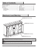
Table of Contents Maximum Load Warning............................................ 2 Safety Information...................................................... 3 Warranty...................................................................... 5 Pre-Assembly.............................................................. 6 Hardware Included ................................................... 6 Product Specifications........................................................ 7 Tools Required.........................
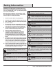
Safety Information Please read and understand this entire manual before attempting to assemble, operate or install the product. If you have any question regarding the product, please call customer service at 1-800-986-3460, 8 a.m.-7 p.m., EST, Monday-Friday, 9 a.m. - 6 p.m., EST, Saturday. WARNING: Under no circumstances should this fireplace be modified. Parts that must be removed for servicing must be replaced prior to operating this fireplace again.
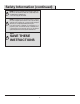
Safety Information (continued) NOTE: Use care in assembling your new fireplace. Take your time and use the hardware provided and a quality Phillips head screwdriver. Never overtighten bolts. • Do not sit on any part of the mantel. NOTE: To avoid injury from unexpected starting or electrical shock, do not plug the power cord into a source of power during unpacking and assembly. The cord must remain unplugged whenever you are adjusting/assembling the fireplace.
Warranty Warranty 1 Year Limited Warranty: The manufacturer warrants that your new Electric Fireplace is free from manufacturing and material defects for a period of one year from date of purchase, subject to the following conditions and limitations. 1. Install and operate this appliance in accordance with the installation and operating instructions furnished with the product at all times. Any unauthorized repair, alteration, willful abuse, accident, or misuse of the product shall nullify this warranty.
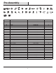
Pre-Assembly HARDWARE INCLUDED KK EE AA BB OO CC PP DD QQ RR SS FF GG HH II JJ TT UU VV WW XX YY LL MM ZZ AAA NN BBB DDD CCC Part Description Part Number Quantity AA Wood Dowel PH-DWLNTL001 41 BB Cam Lock Screw PH-KDBZNC002 25 CC Cam Lock Connector PH-KDCZNC001 25 DD Shelf Pin PH-SPNPCSPLB2 16 EE Handle with Screws Handle with Screws 2 FF Screw- 3 x 12 mm Screw- 3 x 12 mm 40 GG Screw- 4 x 16 mm Screw- 4 x 16 mm 20 HH Slider PH-BDGBLK001 4 II
PRODUCT SPECIFICATIONS VOLTAGE 120VAC, 60 Hz AMPS 12.5 Amps WATTS 1500 Watts NOTE: Hardware not shown to actual size. PLANNING ASSEMBLY Before beginning assembly of product, make sure all parts are present. Compare parts with Hardware Included and Package Contents lists. If any part is missing or damaged, do not attempt to assemble, install or operate the product. Contact customer service for replacement parts. Estimated Assembly Time: 90 Minutes TOOLS REQUIRED Phillips Screwdriver 7 HOMEDEPOT.
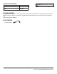
Pre-Assembly (continued) PACKAGE CONTENTS NOTE: All panels are labeled left G and right as viewed from the front of unit.
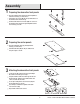
Assembly 1 Preparing the decorative front panels Place the Left Decorative Front Panel (I) and Right Decorative Front Panel (L) on a flat surface. Insert Cam Lock Screws (BB) into the pre-drilled holes in the Left Decorative Front Panel (I). Continue until all Cam Lock Screws (BB) are secured on the Left Decorative Front Panel (I) and Right Decorative Front Panel (L) as shown. BB I L 2 Preparing the center panels Place the Left Center Panel (E) and Right Center Panel (F) on a flat surface.
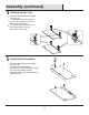
Assembly (continued) 4 Attaching the door catch Flip the right and left center panel assemblies from step 3 over. Locate the Magnetic Door Catch (OO) and secure it to the assembly using Screws (SS). Repeat on the other assembly. Locate the Door Bumper (TT) and secure it to the assembly using the Screws (SS). Repeat on the other assembly. SS E OO SS TT F 5 Preparing the center panels Flip the right and left center panel assemblies from step 4 over.
Assembly (continued) 6 Preparing the center shelf Locate the Center Shelf (R). Insert Wood Dowels (AA) into the pre-drilled holes along the edges of the Center Shelf (R). R AA 7 Preparing the center shelf Locate the Center Shelf Front Panel (Q). Insert Cam Lock Screws (BB) into the predrilled holes in the Center Shelf Front Panel (Q) and secure using a Phillips screwdriver. BB Q 8 Assembling the center shelf Locate the Center Shelf (R) and Center Shelf Front Panel (Q).
Assembly (continued) 9 Preparing the center assembly Locate the Left Center panel assembly (E) and Right Center panel assembly (F) from Step 5, and Center Shelf assembly (R,Q) from Step 8. Using the Left Center panel assembly (E) and the Center Shelf assembly (R,Q) align the pre-installed dowels and cam lock screws into the holes. Secure by inserting Cam Lock Connectors (CC) into the pre-drilled holes as shown. Use a Phillips screwdriver to tighten all the Cam Lock Connectors (CC).
Assembly (continued) 12 Preparing the back base panel 13 Attaching the base panels Insert Wood Dowels (AA) into the pre-drilled holes along the edges of the Back Apron (T) and Left and Right Apron (U,V). Align the Right Right Apron (V) with the Back Apron (T), push together. Secure with the Screws (DDD) using a Phillips screwdriver. Repeat to attach the Left Apron (U).
Assembly 16 Attaching the decorative base panel Insert Screws (DDD) and Washers (JJ) to secure the Decorative Base Panel (X). Tighten using a Phillips screwdriver. JJ DDD X 18 Preparing the side panels 17Attaching the base Insert Wood Dowels (AA) into the pre-drilled holes in the Left Side Panel (D). Repeat for the Right Side Panel (H). Align the Base (A) and the center assembly together. Insert Screws (II) through the bottom of the Base (A) and securely tighten using a Phillips screwdriver.
Assembly (continued) 19 Securing the side panels Base/Center assembly (Step 8) Locate the Base/Center assembly from step 8. Align the Left Side Panel (D) to the base/center assembly and secure together using Screws (II) and a Phillips screwdriver. Repeat to attach the Right Side Panel (H). H D II 20 Attaching the surround bracket Align the Metal Plate (ZZ) onto the back of the center shelf (Q) and secure with a Screw (FF).
Assembly (continued) 21 Preparing the top apron Place the Top Apron (O) on a flat surface. Insert the Screws (GG) through the 2 Hole Plastic Connector Blocks (UU). GG UU O 22 Installing the top apron Align the Top Apron (O) to the main assembly and slide it down onto the pre-installed wood dowels. Secure 2 Hole Plastic Connector Blocks (UU) to the Top Apron (O) and main assembly using Screws (GG) and a Phillips screwdriver.
Assembly (continued) 23 Preparing the top of the assembly AA Insert Wood Dowels (AA) into the pre-drilled holes in the top edges of the main assembly. 24 Preparing the top assembly Place the Top Assembly (G) onto a flat surface. Insert the Cam Lock Screws (BB) into the pre-drilled holes in the bottom of the Top Assembly (G). Tighten using a Phillips Screwdriver. BB 25 Attaching the top assembly G CC G Place the Top Assembly (G) on top of main assembly.
Assembly (continued) 26 Attaching the rolling door hanger 27 Attaching the handles Place the Rolling Door Hangers (KK) on the outside of the Left Sliding Door (J). Insert Bolts (VV) with Flat Washers (JJ) into the predrilled holes. Tighten using a Phillips Screwdriver. Repeat for the Right Sliding Door (K). Remove the pre-assembled screws from the Handles (EE), then attach to the Left Sliding Door (J). Repeat for the Right Sliding Door (K).
Assembly (continued) 29 Attaching the door stopper LL Insert the Bolts (MM) through the roller track to secure the Door Stoppers (LL). MM 30 Attaching the track guide Insert Screws (GG) through the Sliders (HH) into the predrilled holes in the Right Sliding Door (K). Repeat for the Left Sliding Door (J). J K HH GG 19 HOMEDEPOT.COM/HOMEDECORATORS Please contact 1-800-986-3460 for further assistance.
Assembly (continued) 31 Installing the back panels Insert the Screws (FF) through the pre-drilled holes in the Center Back Panel (P) and the Side Back Panels (M). Tighten using a Phillips Screwdriver. P FF M M 32 Attaching the adjustable shelves Insert the Shelf Pins (DD) into the pre-drilled holes on the inside of the Left Side Panel (D) and the Left Center Panel (E). Rest the Adjustable Shelf (N) on the Shelf Pins (DD). Repeat for the right side.
Assembly (continued) 33 Attaching the doors Insert the Right and Left Pin Hinges (PP,QQ). Slide the Left Door (B) into the grooves. Insert Screws (RR) to secure the Left Door (B) into place. Repeat to attach the Right Door (C). QQ PP C PP B QQ RR PP 34 Preparing the insert brackets Remove the Insert Mounting Brackets (YY) by unscrewing the mounting screws from the Left Decorative Front Panel (I) Repeat on the other side. I 21 HOMEDEPOT.
Assembly (continued) the fireplace insert into 35 Installing the mantel assembly Lift the Fireplace Insert (S) carefully into the back of the unit and center in the fireplace insert opening. Do not drag the fireplace insert across the Base as it may scratch your unit. S 36 Securing the fireplace insert Align the Insert Mounting Brackets (YY) from step 24 and secure with the mounting screws. Repeat for the other sides.
Assembly (continued) 37 Adjusting the levelers To level your assembled media unit, turn the Levelers (WW), as needed. The pre-attached Levelers (WW) are located under the base of the media unit. WW 23 HOMEDEPOT.COM/HOMEDECORATORS Please contact 1-800-986-3460 for further assistance.
Assembly (continued) 38 Installing the tipping restraint hardware When the Tipping Restraint Hardware (NN) is properly installed, it can provide protection against unexpected tipping of the Unit due to small tremors, bumps or climbing. Your Unit comes with two Tipping Restraint Hardware (NN). Each Tipping Restraint Hardware (NN) includes one Unit Anchor, one Wall Anchor, one Anchor Tether, and four Anchor Screws. Use these to complete the following steps for a proper installation.
Operation Operation NOTE: The control panel can be accessed at the upper-right corner of the insert. 1 Powering the fireplace 2 Push the Power button to supply power to all functions of the fireplace and put the insert in a standby mode. Push the Power button again to turn off all functions.
Operation (continued) 5 Replacing the remote control battery 6 Disposing of used batteries The battery may contain hazardous substances that could endanger the environment and human health. When the remote control stops operating or its range seems reduced, it is time to replace the battery with new ones. On the back end of the remote, press and slide the battery door open and remove the old battery. Insert 2 AAA batteries, checking that the + and sides of the battery match inside the battery compartment.
Operation (continued) 8 Patent pending Safer Plug™ information This product is equipped with a Safer Plug™, which is an advanced safety device that helps detect electrical fires caused from faulty outlets. Overloading of outlets, adapters and surge protectors may cause overheating, damage, and increased risk of fires. The Safer Plug continuously monitors the temperature in the plug and outlet and will turn off the heater to prevent unsafe outlet overheating.
FCC/IC Information WARNING: Changes or modifications to this unit not expressly approved by the party responsible for compliance could void user’s authority to operate the equipment. NOTE: This equipment has been tested and found to comply with the limits for Class B digital device, pursuant to part 15 of the FCC Rules. These limits are designed to provide reasonable protection against harmful interference in a residential installation.
Troubleshooting PROBLEM ROOT CAUSE CORRECTIVE ACTION Display shows " " The thermostat sensor is broken or disconnected. Unplug the fireplace, remove the back panel of the fireplace and check that the thermostat is plugged into the main circuit board. If this does not solve the problem contact customer service for a replacement thermostat sensor. Display shows " " The thermostat sensor is broken. Contact customer service for a replacement thermostat sensor.
Troubleshooting (continued) PROBLEM Flame effect works but heater function does not and the emberbed flashes when the Heater button is pressed. ROOT CAUSE CORRECTIVE ACTION The heater is disabled. With the power on press and hold the POWER button on the control panel for 10 seconds. Once re-enabled the emberbed lights will flash multiple times. There are no batteries. Change the remote batteries. The signal is poor. Operate remote transmitter at a slow measured pace.
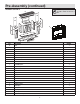
Replacement Parts For replacement parts, call our customer service department at 1-800-986-3460, 8 a.m.-7 p.m., EST, Monday-Friday, 9 a.m. - 6 p.m., EST, Saturday. Part 1 2 3 4 5 6 7 8 9 10 11 Description Qty.
Questions, problems, missing parts? Before returning to the store call Home Decorators Customer Service 8 a.m. - 7 p.m., EST, Monday - Friday, 9 a.m. - 6 p.m., EST, Saturday 1-800-986-3460 HOMEDEPOT.COM/HOMEDECORATORS RETAIN THIS MANUAL FOR FUTURE USE.