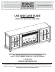
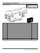
690 462/89468/26MM8682-Z318 USE AND CARE GUIDE WESTCLIFF ELECTRIC FIREPLACE QUESTIONS, PROBLEMS, MISSING PARTS? BEFORE RETURNING TO THE STORE, CALL HOME DECORATORS COLLECTION CUSTOMER SERVICE 8 A.M. - 7 P.M., EST, MONDAY - FRIDAY, 9 A.M. - 6 P.M., EST, SATURDAY 1-800-986-3460 HOMEDEPOT.COM/HOMEDECORATORS THANK YOU We appreciate the trust and confidence you have placed in Home Decorators through the purchase of this electric fireplace.
Table of Contents Maximum Load Warning............................................ 2 Safety Information...................................................... 3 Warranty...................................................................... 5 Pre-Assembly.............................................................. 6 Hardware Included ................................................... 6 Product Specifications........................................................ 6 Tools Required.........................
Safety Information Please read and understand this entire manual before attempting to assemble, operate or install the product. If you have any question regarding the product, please call customer service at 1-800-986-3460, 8 a.m.-7 p.m., EST, Monday-Friday, 9 a.m. - 6 p.m., EST, Saturday. WARNING: This appliance is hot when in use. To avoid burns, do not touch hot surfaces with bare skin. If provided, use handles when moving this appliance.
Safety Information (continued) NOTE: Use care in assembling your new fireplace. Take your time and use the hardware provided and a quality Phillips head screwdriver. Never overtighten bolts. • Do not sit on any part of the mantel. NOTE: To avoid injury from unexpected starting or electrical shock, do not plug the power cord into a source of power during unpacking and assembly. The cord must remain unplugged whenever you are adjusting/assembling the fireplace.
Warranty 1 Year Limited Warranty: The manufacturer warrants that your new Electric Fireplace is free from manufacturing and material defects for a period of one year from date of purchase, subject to the following conditions and limitations. 1. Install and operate this appliance in accordance with the installation and operating instructions furnished with the product at all times. Any unauthorized repair, alteration, willful abuse, accident, or misuse of the product shall nullify this warranty. 2.
Pre-Assembly HARDWARE INCLUDED AA II HH Part AA BB CC DD EE FF GG HH II JJ KK LL ZZ CC BB JJ DD KK Description Shelf Pin Euro Hinge Small Flathead Screw Camlock Bolt Camlock Metal Plate (Pre-attached) Screw Wood Dowel Leveler (Pre-attached) Door Bumper Knob (With screw) Cover Touch-up Pen EE LL Part Number PH-SPNPCSPLB2 PH-HNGPC35AS95 N/A PH-KDBZNC002 PH-KDCZNC002 PH-PLBLK001 PH-SCRBLK001 PH-DWLNTL001 PH-LVRBLK001 PH-BMPCLR001 N/A N/A N/A FF GG ZZ Quantity 8 4 24 24 24 2 26 28 6 4 2 8 1 NOTE:
Pre-Assembly (continued) PACKAGE CONTENTS NOTE: All panels are labeled left and right as viewed from the front of unit.
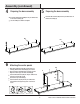
Assembly 1 2 Preparing the front panel Attaching the front panel Insert the Wood Dowels (HH) into the pre-drilled holes in the Left Center Panel (D). Align the Left Front Panel (B) and the Left Center Panel (D) and push together. To secure into place, insert the Camlocks (EE) into the pre-drilled holes and tighten with the Phillips Screwdriver. Repeat this process for the Right Front Panel (C) and Right Center Panel (E). Put the Left Front Panel (B) down on a flat surface.
Assembly (continued) 4 5 Preparing the base assembly Preparing the base assembly Insert the Wood Dowels (HH) into the pre-drilled holes in the Base Assembly (A). Insert the Camlock Bolts (DD) into the pre-drilled holes in the Base Assembly (A). Use the Phillips Screwdriver to tighten. DD HH A 6 A Attaching the center panels Align the Left Center Panel (D) and the Left Front Panel (B) with the Base Assembly (A). Push down.
Assembly (continued) 7 Securing the panels To secure the Middle Front Panel (F) to the Left Front Panel (B), insert the Screws (GG) through the Metal Plate (FF) and turn clockwise to tighten. Repeat steps to secure the Middle Front Panel (F) to the Right Front Panel (C). FF C GG F B 8 Attaching the side panels Push the Left Side Panel (H) down onto the Base Assembly (A). Insert the Camlocks (EE) into the pre-drilled holes in the Left Side Panel (H). Use the Phillips Screwdriver to tighten.
Assembly (continued) 9 10 Preparing the top assembly Preparing the top assembly Insert the Camlock Bolts (DD) through the pre-drilled holes in the Top Assembly (G). Use the Phillips Screwdriver to tighten the Camlock Bolts (DD). Insert the Wood Dowels (HH) into the pre-drilled holes in the Panels (D) (E) (F) (H) (I). HH F H D DD E I G 11 Attaching the top assembly Align the Top Panel (G) with the Panels (D) (E) (F) (H) (I). Push down to connect. Insert the Camlocks (EE) into the pre-drilled holes.
Assembly (continued) 12 Attaching the cover 13 Attaching the back panels Peel the back off the Covers (LL) and place over the Camlocks (EE) screwed into the Panels (D) (E) (H) (I). Insert the Screws (GG) through the pre-drilled holes in the Back Panels (J). H D E J I EE GG J LL 14 Preparing the doors Put the Left Door (K) on a flat surface. Insert the Small Flathead Screws (CC) through the Euro Hinges (BB) to connect to the Left Door (K).
Assembly (continued) 15 Attaching the knobs KK Insert the screws through the pre-drilled holes in the Right Door (L), to attach the Knobs (KK). Repeat for the Left Door (K). K L 16 Attaching the doors Align the Right Door (L) with the Right Side Panel (I). Insert the Small Flathead Screws (CC) through the Euro Hinge (BB). Use the Phillips Screwdriver to tighten. Repeat to attach the Left Door (K) to the Left Side Panel (H). CC BB I H L K 13 HOMEDEPOT.
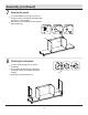
Assembly (continued) the fireplace insert 17 Attaching the adjustable shelves 18 Installing into the mantel assembly Insert the Shelf Pins (AA) into the pre-drilled holes on the inside of the Panels (D) (E) (H) (I). Rest the Adjustable Shelves (M) on the Shelf Pins (AA). Lift the Fireplace Insert (O) carefully into the back of the unit and center in the fireplace insert opening. Do not drag the fireplace insert across the Base Assembly (A) as it may scratch your unit.
Assembly (continued) 20 Attaching the securing block Place the Securing Block (N) onto the Camlock Bolts (DD) and the Wood Dowels (HH). Insert the Camlocks (EE) into the pre-drilled holes. Turn clockwise with the Phillips Screwdriver to secure. EE N DD EE HH 21 Leveling the unit On the bottom side of each foot, are the Levelers (II). Turn them until the unit is balanced. II 15 HOMEDEPOT.COM/HOMEDECORATORS Please contact 1-800-986-3460 for further assistance.
Operation NOTE: The control panel can be accessed at the upper-right corner of the insert. When a function is changed from the control panel or remote control there will be a corresponding indicator (see Figure 1) on the upper-right of the projection screen. The indicator shows the function changed and the level selected by the control panel or remote control. When the function is turned off, the corresponding indicator will flash several times and then fade off. Fig .
Operation (continued) 5 Replacing the remote control battery 6 Disposing of used batteries The battery may contain hazardous substances that could endanger the environment and human health. When the remote control stops operating or its range seems reduced, it is time to replace the battery with new ones. On the back end of the remote, press and slide the battery door open and remove the old battery. Insert 2 AAA batteries, checking that the + and sides of the battery match inside the battery compartment.
FCC/IC Information WARNING: Changes or modifications to this unit not expressly approved by the party responsible for compliance could void user’s authority to operate the equipment. NOTE: This equipment has been tested and found to comply with the limits for Class B digital device, pursuant to part 15 of the FCC Rules. These limits are designed to provide reasonable protection against harmful interference in a residential installation.
Troubleshooting PROBLEM ROOT CAUSE CORRECTIVE ACTION Display shows " " The thermostat sensor is broken or disconnected. Unplug the fireplace, remove the back panel of the fireplace and check that the thermostat is plugged into the main circuit board. If this does not solve the problem contact customer service for a replacement thermostat sensor. Display shows " " The thermostat sensor is broken. Contact customer service for a replacement thermostat sensor.
Troubleshooting (continued) PROBLEM Flame effect works but heater function does not and the emberbed flashes when the Heater button is pressed. ROOT CAUSE CORRECTIVE ACTION The heater is disabled. With the power on press and hold the POWER button on the control panel for 10 seconds. Once re-enabled the emberbed lights will flash multiple times. There are no batteries. Change the remote batteries. The signal is poor. Operate remote transmitter at a slow measured pace.
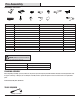
Replacement Parts For replacement parts, call our customer service department at 1-800-986-3460, 8 a.m.-7 p.m., EST, Monday-Friday, 9 a.m. - 6 p.m., EST, Saturday. Part Description Qty.
Questions, problems, missing parts? Before returning to the store call Home Decorators Customer Service 8 a.m. - 7 p.m., EST, Monday - Friday, 9 a.m. - 6 p.m., EST, Saturday 1-800-986-3460 HOMEDEPOT.COM/HOMEDECORATORS RETAIN THIS MANUAL FOR FUTURE USE.