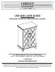
004151434/308824353/19WM30692-TF969 USE AND CARE GUIDE MARSHFIELD ELECTRIC FIREPLACE WALL MANTEL QUESTIONS, PROBLEMS, MISSING PARTS? BEFORE RETURNING TO THE STORE, CALL HOME DECORATORS COLLECTION CUSTOMER SERVICE 8 A.M. - 7 P.M., EST, MONDAY - FRIDAY, 9 A.M. - 6 P.M., EST, SATURDAY 1-800-986-3460 HOMEDEPOT.COM/HOMEDECORATORS THANK YOU We appreciate the trust and confidence you have placed in Home Decorators through the purchase of this electric fireplace.
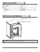
Table of Contents Maximum Load Warning............................................ 2 Safety Information...................................................... 3 Warranty...................................................................... 5 Pre-Assembly.............................................................. 6 Hardware Included ................................................... 6 Product Specifications........................................................ 6 Tools Required.........................
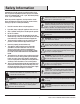
Safety Information Please read and understand this entire manual before attempting to assemble, operate or install the product. If you have any question regarding the product, please call customer service at 1-800-986-3460, 8 a.m.-7 p.m., EST, Monday-Friday, 9 a.m. - 6 p.m., EST, Saturday. WARNING: Under no circumstances should this fireplace be modified. Parts that must be removed for servicing must be replaced prior to operating this fireplace again.
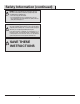
Safety Information (continued) NOTE: Use care in assembling your new fireplace. Take your time and use the hardware provided and a quality Phillips head screwdriver. Never overtighten bolts. • Do not sit on any part of the mantel. • It is recommended to work on a soft surface like a rug or to lay out a blanket to protect the furniture from getting scratched during the assembly process.
Warranty Warranty 1 Year Limited Warranty: The manufacturer warrants that your new Electric Fireplace is free from manufacturing and material defects for a period of one year from date of purchase, subject to the following conditions and limitations. 1. Install and operate this appliance in accordance with the installation and operating instructions furnished with the product at all times. Any unauthorized repair, alteration, willful abuse, accident, or misuse of the product shall nullify this warranty.
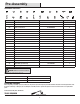
Pre-Assembly HARDWARE INCLUDED AA BB CC DD EE KK LL MM NN OO Part FF PP Description HH GG RR QQ JJ II SS TT UU Part Number Quantity AA Screw 3 x 16mm PH-SCRBLK001 12 BB Camlock Screw PH-KDBZNC001 14 CC Cam Lock Connector PH-KDCZNC001 14 DD Wood Dowel PH-DWLNTL001 18 EE Magnetic Catch PH-MCHBRW001 2 FF Screw 3 x 15mm Screw 3 x 15mm 4 GG Bolt 6.
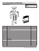
Pre-Assembly (continued) PACKAGE CONTENTS NOTE: All panels are labeled left and right as viewed from the front of unit.
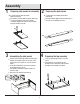
Assembly 1 2 Preparing side panels for assembly Locate the Left Side Panel (B) and the Right Side Panel (C). Insert Cam Lock Screws (BB) into the pre-drilled holes in each panel (B,C) and secure using a Phillips screwdriver. Repeat until all Cam Lock Screws (BB) have been installed as shown. Preparing the back apron Locate the Base Front Rail (D) and the Base Back Rail (E). Insert Wood Dowels (DD) into the pre-drilled holes on the edges of each Rail (D,E) as shown.
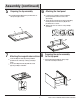
Assembly (continued) 5 6 Preparing the top assembly Insert Wood Dowels (DD) into the pre-drilled holes on the Top Panel (G) as shown. Attaching the front panel Locate the Top Front Rail (F) and align it with the previously installed cam lock screws on the Top Panel (G). Secure the Top Front Rail (F) onto the Top Panel (G) by inserting the Cam Lock Connectors (CC) into the pre-drilled holes as shown. Tighten both cam lock connectors using a Phillips screwdriver.
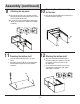
Assembly (continued) 9 Attaching the top panel 10 Place the Top Panel (G) on top of the main assembly while aligning the previously installed cam lock screws and wood dowels with the holes. To secure the screws, insert the Cam Lock Connectors (CC) into the pre-drilled holes. Tighten using a Phillips screwdriver. Preparing the center assembly for the base Insert the Wood Dowels (DD) into the bottom edges of the main assembly as indicated.
Assembly (continued) 13 Attaching the base legs 14 Securing the back panel Locate the Base Left Leg (H) and the Base Right Leg (I). Place the Bolts (GG) through the Flat Washers (HH) and secure through each Leg (H,I) and into the main assembly as shown in the diagram. Tighten each Bolt (GG) using a Phillips screwdriver. Locate the Back Panel (J). Insert the Screws (AA) through the pre-drilled holes in the Back Panel (J) and tighten using a Phillips screwdriver.
Assembly (continued) 17 Attaching the drawer brackets 18 Assembling the drawer box Attach the Black Plastic Brackets (KK) onto the inside of the drawer assembly as shown using the Screws (JJ) and a Phillips screwdriver. Locate the Drawer Front (O). Align the pre-drilled holes on the Drawer Front (O) with the brackets inside the drawer. From inside the drawer, secure the brackets onto the Drawer Front (O) using the Screws (LL) and a Phillips screwdriver.
Assembly (continued) 21 Attaching the door handles 22 Attaching the double doors Remove the pre-assembled screws from the Handles (OO), then attach to the Left Door (P). Repeat for the Right Door (Q). Align the previously installed hinges on the Left Door (P) with the hinges on the left side of the main assembly. Insert Screws (NN) to secure the Left Door (C) into place using a Phillips screwdriver. Repeat to attach the Right Door (Q).
Assembly (continued) 25 Installing the tipping restraint hardware When the Tipping Restraint Hardware (PP) is properly installed, it can provide protection against unexpected tipping of the Unit due to small tremors, bumps or climbing. Your Unit comes with two Tipping Restraint Hardware (PP). Each Tipping Restraint Hardware (PP) includes one Unit Anchor, one Wall Anchor, one Anchor Tether, and four Anchor Screws. Use these to complete the following steps for a proper installation.
Operation Operation NOTE: The control panel can be accessed at the upper-right corner of the insert. 1 Powering the fireplace 2 Push the Power button to supply power to all functions of the fireplace and put the insert in a standby mode. Push the Power button again to turn off all functions. Adjusting the flame There are 6 brightness levels including 00 (OFF) setting that can be selected.
Operation (continued) 5 Replacing the remote control battery 6 Disposing of used batteries The battery may contain hazardous substances that could endanger the environment and human health. When the remote control stops operating or its range seems reduced, it is time to replace the batteries with new ones. On the back end of the remote, press and slide the battery door open and remove the old battery.
Operation (continued) 8 Patent pending Safer Plug® information This product is equipped with a Safer Plug®, which is an advanced safety device that helps detect electrical fires caused from faulty outlets. Overloading of outlets, adapters and surge protectors may cause overheating, damage, and increased risk of fires. The Safer Plug continuously monitors the temperature in the plug and outlet and will turn off the heater to prevent unsafe outlet overheating.
FCC/IC Information WARNING: Changes or modifications to this unit not expressly approved by the party responsible for compliance could void user’s authority to operate the equipment. NOTE: This equipment has been tested and found to comply with the limits for Class B digital device, pursuant to part 15 of the FCC Rules. These limits are designed to provide reasonable protection against harmful interference in a residential installation.
Troubleshooting PROBLEM ROOT CAUSE Display shows “ ” The thermostat sensor is broken or disconnected. Display shows “ ” The thermostat sensor is broken. Display shows “ ” CORRECTIVE ACTION Unplug the fireplace, remove the back panel of the fireplace and check that the thermostat is plugged into the main circuit board. If this does not solve the problem, contact customer service for a replacement thermostat sensor. Contact customer service for a replacement thermostat sensor.
Replacement Parts For replacement parts, call our customer service department at 1-800-986-3460, 8 a.m.-7 p.m., EST, Monday-Friday, 9 a.m. - 6 p.m., EST, Saturday. Part 1 2 3 4 5 6 7 8 9 10 11 Description Qty. Remote Control Flame Circuit Board Flame Spinner Flame Generator Drive Motor Thermostat Sensor Blower/ Heater Assembly Control Panel Circuit Board Front Panel with Flame Embered with Logest Embered Circuit Board Main Power PCB 1 1 1 1 1 1 1 1 1 1 1 20 HOMEDEPOT.
HOMEDEPOT.COM/HOMEDECORATORS Please contact 1-800-986-3460 for further assistance.
HOMEDEPOT.COM/HOMEDECORATORS Please contact 1-800-986-3460 for further assistance.
HOMEDEPOT.COM/HOMEDECORATORS Please contact 1-800-986-3460 for further assistance.
Questions, problems, missing parts? Before returning to the store call Home Decorators Customer Service 8 a.m. - 7 p.m., EST, Monday - Friday, 9 a.m. - 6 p.m., EST, Saturday 1-800-986-3460 HOMEDEPOT.COM/HOMEDECORATORS RETAIN THIS MANUAL FOR FUTURE USE.