006152679/316091919/23MM90587-TPB01 1006152674/316091921/23MM90587-TPG22 1006152673/316091922/23MM90587-PC78 USE AND CARE GUIDE CANTERIDGE ELECTRIC FIREPLACE MEDIA MANTEL QUESTIONS, PROBLEMS, MISSING PARTS? BEFORE RETURNING TO THE STORE, CALL HOME DECORATORS COLLECTION CUSTOMER SERVICE MONDAY - FRIDAY 8 A.M. - 7 P.M. EST, AND SATURDAY 9 A.M. - 6 P.M. EST. 1-800-986-3460 HOMEDEPOT.
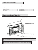
Table of Contents Maximum Load Warning............................................ 2 Safety Information...................................................... 3 Warranty...................................................................... 5 Pre-Assembly.............................................................. 6 Hardware Included ................................................... 6 Product Specifications........................................................ 6 Tools Required.........................
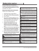
Safety Information Please read and understand this entire manual before attempting to assemble, operate or install the product. If you have any question regarding the product, please call customer service at 1-800-986-3460, Monday-Friday 8 A.M. - 7 P.M. EST, and Saturday 9 A.M. - 6 P.M. EST. WARNING: Under no circumstances should this fireplace be modified. Parts that must be removed for servicing must be replaced prior to operating this fireplace again.
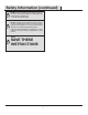
Safety Information (continued) NOTE: Use care in assembling your new fireplace. Take your time and use the hardware provided and a quality Phillips head screwdriver. Never overtighten bolts. • Do not sit on any part of the mantel. NOTE: To avoid injury from unexpected starting or electrical shock, do not plug the power cord into a source of power during unpacking and assembly. The cord must remain unplugged whenever you are adjusting/assembling the fireplace.
Warranty Warranty 1 Year Limited Warranty: The manufacturer warrants that your new Electric Fireplace is free from manufacturing and material defects for a period of one year from date of purchase, subject to the following conditions and limitations. 1. Install and operate this appliance in accordance with the installation and operating instructions furnished with the product at all times. Any unauthorized repair, alteration, willful abuse, accident, or misuse of the product shall nullify this warranty.
Pre-Assembly HARDWARE INCLUDED AA BB CC DD II JJ KK LL Part Description EE FF MM NN GG HH Part Number Quantity AA Screw 4 x 50 mm PH-SCRBLK006 14 BB Screw 3 x 12 mm PH-SCRBLK007 2 CC Magnetic Catch PH-MCHBRW001 2 DD Screw 3 x 15 mm PH-SCRBLK010 4 EE Screw 3.
Pre-Assembly (continued) PACKAGE CONTENTS NOTE: All panels are labeled left and right as viewed from the front of unit.
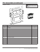
Assembly 1 Attaching the center fireplace surround Locate the Top Surround Rail (C) as well as the Left and Right Partitions (B and D). Align the Top Surround Rail (C) between the Left and Right Partitions (B and D). Push together, inserting the pre-installed dowels on the Top Surround Rail (C) into the holes on the Left and Right Partitions (B and D) as shown. Insert Screws (BB) through the pre-drilled holes on the edges of Partitions (B and D) and Metal Plate (LL) as shown.
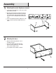
Assembly (continued) 3 Attaching the side panel Align the Left and Right Side Panels (E and F) with the Bottom Shelf (A). Insert Screws (AA) through the Bottom Shelf (A) and into the pre-drilled holes on the edges of the Left and Right Side Panels (E and F) as shown. F Securely tighten using a Phillips screwdriver. E A AA 4 Attaching the back panels Set the cabinet upright gently. H Locate the Back Panels (H).
Assembly (continued) 5 Attaching door handles Locate the Cabinet Doors (N and O). Each Door Handle (GG) has pre-attached screws. Remove these screws and place handles over the pre-drilled holes in each Cabinet Door (N and O). O Place the pre-attached screws on the other side of the Cabinet Doors (N and O) and tighten with a Phillips screwdriver through the door and into the handle.
Assembly (continued) 7 Assembling the top panel Locate the Top Panel (G) and the Left, Center, and Right Media Shelf Partitions (I, J, K). Align the Left Media Shelf Partition (I) with the screw holes beneath the Top Panel (G). After inserting the screw on the Left Media Shelf Partition (I) into the hole, tighten the fastener using a Phillips Screwdriver as shown. Repeat steps to secure Center Media Shelf Partition (J) and Right Media Shelf Partition (K).
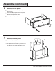
Assembly (continued) 9 Attaching the door catches Locate the Center Shelf (M) and place on a flat surface. Attach the Magnetic Door Catches (CC) to the Center Shelf (M) using Screws (DD) where indicated by the diagram. DD CC M 10 Attaching the center shelf Align the Center Shelf (M) with the top assembly. Insert Screws (AA) through the Center Shelf (M) and into the pre-drilled holes on the edges of the Left, Center, and Right Media Shelf Partitions (I, J, K) as shown.
Assembly (continued) 11 Attaching the top Align the main assembly with the screw holes beneath the Center Shelf (M). After inserting the screws into the holes, tighten the fasteners using a Phillips Screwdriver as shown. Securely fasten each screw on the main assembly to the Center Shelf (M). M 12 Securing the top panel Be sure that all fasteners are tightened by getting behind the unit to tighten the fasteners toward the front. Secure each with a Phillips screwdriver.
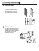
Assembly (continued) 13 Securing the back panels Place the Back Panel Brackets (FF) between the back panels and the grooves of the assembly as shown. Fasten each Back Panel Bracket (FF) using Screws (EE). Repeat until all brackets are in place as indicated by the diagram. EE FF 14 Inserting the adjustable shelves Locate the two Adjustable Shelves (P). Insert the Shelf Pins (HH) into the pre-drilled holes on the inside of each cabinet side panel at your desired height.
Assembly (continued) 15 Attaching the cabinet doors Lift the Fireplace Insert (Q) carefully into the back of the unit and center in the fireplace insert opening. Do not drag the Fireplace Insert (Q) across the base as it may scratch your unit. Q 16 Securing the fireplace insert Align the Metal Brackets (II) behind the fireplace insert and above the pre-drilled holes. Secure with the Mounting Screws (JJ) on both sides. JJ II 15 HOMEDEPOT.
Assembly (continued) 17 Installing the tipping restraint hardware When the Tipping Restraint Hardware (KK) is properly installed, it can provide protection against unexpected tipping of the Unit due to small tremors, bumps or climbing. Wall Each Tipping Restraint Hardware (KK) includes one Unit Anchor, one Wall Anchor, one Anchor Tether, and four Anchor Screws. Use these to complete the following steps for a proper installation. KK Locate a secure wall stud behind the unit closest to the left side.
Operation Operation NOTE: The control panel can be accessed at the upper-right corner of the insert. 1 Powering the fireplace 2 Push the Power button to supply power to all functions of the fireplace and put the insert in a standby mode. Push the Power button again to turn off all functions. Adjusting the flame There are 6 brightness levels that can be selected: Settings F6 - F4 decrease in Amber brightness. Settings F3 - F1 decrease in Spectrafire brightness.
Operation (continued) 5 Replacing the remote control battery 6 Disposing of used batteries The battery may contain hazardous substances that could endanger the environment and human health. When the remote control stops operating or its range seems reduced, it is time to replace the battery with new ones. On the back end of the remote, press and slide the battery door open and remove the old battery.
Operation (continued) 8 Patented Safer Plug® information This product is equipped with a Safer Plug®, which is an advanced safety device that helps detect electrical fires caused from faulty outlets. Overloading of outlets, adapters and surge protectors may cause overheating, damage, and increased risk of fires. The Safer Plug continuously monitors the temperature in the plug and outlet and will turn off the heater to prevent unsafe outlet overheating.
FCC/IC Information WARNING: Changes or modifications to this unit not expressly approved by the party responsible for compliance could void user’s authority to operate the equipment. NOTE: This equipment has been tested and found to comply with the limits for Class B digital device, pursuant to part 15 of the FCC Rules. These limits are designed to provide reasonable protection against harmful interference in a residential installation.
Troubleshooting PROBLEM Fireplace stopped heating before reached desired temperature. ROOT CAUSE CORRECTIVE ACTION Fireplace has reached set temperature. Temperature around fireplace might be a few degrees higher than other area in the room. Set the fireplace to a higher temperature or always “on”. Display shows " " The thermostat sensor is broken or disconnected. Unplug the fireplace, remove the back panel of the fireplace and check that the thermostat is plugged into the main circuit board.
Troubleshooting (continued) PROBLEM Flame effect works but heater function does not and the emberbed flashes when the Heater button is pressed. ROOT CAUSE CORRECTIVE ACTION The heater is disabled. With the power on press and hold the Power button on the control panel for 10 seconds. Once re-enabled the emberbed lights will flash multiple times. There are no batteries. Change the remote batteries. The signal is poor. Operate remote transmitter at a slow measured pace.
Replacement Parts For replacement parts, call our customer service department at 1-800-986-3460, Monday - Friday 8 A.M. - 7 P.M. EST, and Saturday 9 A.M. - 6 P.M. EST. Part 1 2 3 4 5 6 7 8 9 10 11 Description Qty.
HOMEDEPOT.COM/HOMEDECORATORS Please contact 1-800-986-3460 for further assistance.
Questions, problems, missing parts? Before returning to the store call Home Decorators Customer Service Monday - Friday 8 A.M. - 7 P.M. EST, and Saturday 9 A.M. - 6 P.M. EST. 1-800-986-3460 HOMEDEPOT.COM/HOMEDECORATORS RETAIN THIS MANUAL FOR FUTURE USE.