
Installation Guide


10
Assembly - Hanging the Fan (continued)
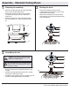
Installing the receiver
6
□ Position the house supply wires (AAA) to one side of the
slide-on mounting bracket (A); position the fan wires (BBB)
to the opposite side.
□ Insert the narrow end of the receiver (K) (as shown, at side
towards the ceiling) into the slide-on mounting bracket until
it rests on top of the ball/downrod assembly.
WARNING: To reduce the risk of re or electric shock,
remember to disconnect power. The electrical wiring must
meet all local and national electrical code requirements.
The electrical source and fan must be 110/120 volt, 60Hz.
Do not use this product in conjunction with any variable wall
control. Incorrect wire connection can damage this receiver.
CAUTION: If other fan wires are a different color, have this
unit installed by a licensed electrician.
CAUTION: Do not install the receiver in a damp location or
immerse in water (For indoor use only). Do not pull on or cut
the receiver leads shorter. Do not drop or bump the unit.
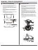
Setting the remote control codes
5
NOTE: The frequencies on your receiver and hand unit have
been preset at the factory. Before installing the receiver, make
sure the dip switches on the receiver and hand unit are set
to the same frequency. The dip switches on the hand unit are
located inside the battery compartment.
NOTE: The battery will weaken with age and should be
replaced before leaking takes place as this will damage the
hand unit. Dispose of the used battery properly and keep the
battery out of the reach of children.
NOTE: It is imperative that the code used for both transmitter
and receiver is exactly the same, otherwise remote controller
will not work.
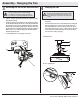
□ Setting the Code on the Remote
□ Remove the battery cover on the back of the remote control
(L) by pressing rmly on the arrow and sliding the cover off.
□ Slide the code switches to your choice of either up or down.
The factory setting is up.
□ From the factory, the remote displays °F, press the dip
switch °C/°F to display °C.
□ For fans with incandescent bulbs or dimmable LED bulbs,
slide the dip switch O/D to the position marked “D”, if you
are not using incandescent bulbs or dimmable LED bulbs
slide the dip switch to the “O” position.
□ Install 2 AAA batteries (included).
□ Replace the battery cover on the remote control (L).
□ Setting the Code on the Receiver
□ Slide the code switches on the receiver (K) to the same
positions as set on the remote control (L).
1 2 3
ON
4
1 2 3 4
ON
D
O
L
ZZ
°C/°F
Antenna
DIP
K
AAA
BBB
A
K
B
C