
Full Product Manual


12
Assembly - Attaching the Light Kit
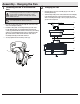
Installing the light kit tter assembly
2
□ Remove one screw (QQ) from the light kit pan (I) and
loosen, but do not remove the other two screws.
□ Connect the wires from the light kit tter assembly (J) to
the wires from the fan motor assembly (E) by connecting
the molded adaptor plugs together. Carefully tuck all wires
and splices into the switch cup.
□ Push the light kit tter assembly (J) up to the light kit
pan (I) so that the two loosened screw heads t into
the keyhole slots. Turn the light kit tter assembly (J)
clockwise to secure.
□ Re-install the screw (QQ) that was removed in step 1.
□ Make sure all the screws are rmly tightened.
CAUTION: To reduce the risk of electric shock, disconnect
the electrical supply circuit to the fan before installing the
light kit pan.
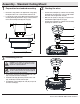
Installing the shatter resistant bowl
3
□ Place the shatter resistant bowl (K) into the light kit pan (I),
aligning the three at areas on the top ange of the shatter
resistant bowl (K) with the three raised dimples in the light
kit pan.
□ Turn the shatter resistant bowl (K) clockwise until it stops.
CAUTION: Make sure the power is off before attaching or
removing the shatter resistant bowl.
WARNING: Allow the shatter resistant bowl to cool completely
before removing.
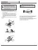
□ Remove one screw (NN) from the black bracket below the fan
motor assembly (E). Loosen but do not remove the other two
screws.
□ Attach the light kit pan (I) to the fan motor assembly (E) by
securing with the two screws (NN) loosened in the rst step.
Push the light kit pan (I) up to engage the screw heads in the
screw slots and turn to secure. Tighten each screw rmly.
Attaching the light kit pan
1
E
I
NN
I
K
I
J
QQ