Item # 1005228146 Model # 269-218-463-Y USE AND CARE GUIDE BARDEN COLLECTION: ELECTRIC FIREPLACE MEDIA MANTEL IMPORTANT INSTRUCTIONS PLEASE READ THIS MANUAL BEFORE INSTALLING AND USING APPLIANCE WARNING! IF THE INFORMATION IN THIS MANUAL IS NOT FOLLOWED EXACTLY, AN ELECTRICAL SHOCK OR FIRE MAY RESULT CAUSING PROPERTY DAMAGE, PERSONAL INJURY OR LOSS OF LIFE. INSTALLER: Leave this manual with the appliance. CONSUMER: Retain this manual for future reference.
Table of Contents Table of Contents. . . . . . . . . . . . . . . . . . . . . . . . . . . . . . . . . . . . . 2 Warranty . . . . . . . . . . . . . . . . . . . . . . . . . . . . . . . . . . . . . . . . . . . 2 Pre-Assembly . . . . . . . . . . . . . . . . . . . . . . . . . . . . . . . . . . . . . . . 3 Planning Assembly. . . . . . . . . . . . . . . . . . . . . . . . . . . . . . . . . . 3 Tools Required . . . . . . . . . . . . . . . . . . . . . . . . . . . . . . . . . . . . . 3 Hardware Included. . . . . . . .
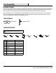
Pre-Assembly PLANNING ASSEMBLY efore you begin assembly, locate the instructions and hardware. Compare all parts with the Hardware Included and Package Contents lists. B Be sure you have all the parts and can identify them. A helping hand is always good. Assemble your mantel with an adult assistant if possible. Some pieces are heavy and will need to be held by a helper. Assembly time will take approximately 30-60 minutes. efore assembly, use scissors to unwrap the parts from the packaging.
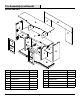
Pre-Assembly (continued) PACKAGE CONTENTS P A N F D M Q G C H P L L K M J E Q B Part Description Quantity Part Description Quantity A Top Panel 1 J Right Inside Panel 1 B Base Panel 1 K Front Firebox Support 1 C Media Shelf 1 L Firebox Support 2 D Left Side Panel 1 M Adjustable Shelf 2 E Right Side Panel 1 N Upper Back Panel 1 F Left Upper Inside Panel 1 P Back Panel 2 G Right Upper Inside Panel 1 Q Cabinet Door 2 H Left Inside Panel 1 4
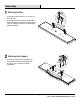
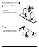
Assembly the Base 1 Attaching □ Locate the base panel (B) and place on a soft surface to protect the finish. □ Locate the base panel (B). Attach the insert panel (K) to the base panel (B) by inserting two bolts (AA) through the connectors and turning clockwise. Do not strip the bolts (AA) by overtightening. AA K B Insert Support 2 Attaching □ AA Locate the two insert supports (L) and attach to the base panel (B) by inserting two bolts (AA) through the connectors.
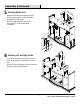
Assembly (continued) Left and Right Inside 3 Attaching Panel □ Locate the Left and Right Inside Panel (H & J) and attach to the base panel (B) by inserting four dowels (BB) into the provided holes. □ Insert two bolts (AA) through the connectors and turn clockwise. Do not strip the bolts (AA) by overtightening.
Assembly (continued) Media Shelf 5 Attaching □ Attach the left and right side panel (D & E) and media shelf (C) to the base panel assembly by inserting four dowels (BB) in the provided holes. □ Insert six bolts (AA) through the connectors and turn clockwise. Do not strip the bolts (AA) by overtightening.
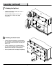
Assembly (continued) the Top Panel 7 Attaching □ Locate the top panel (A) and carefully place on top of the media shelf assembly. □ Insert six bolts (AA) through the connectors and turn clockwise. Do not strip the bolts (AA) by overtightening. A AA D F G E AA 8 Attaching the Back Panels □ Locate the upper back panel (N) and one align it with the back of the media console with the finished side facing up. Insert and tighten fourteen back panel screws (CC) to the media console.
Assembly (continued) 9 Preparing the Doors □ Locate the two doors (Q) and place on a soft surface to protect the finish. □ Attach the two hinges to the doors (Q) by inserting four hinge screws (HH). Repeat this step for the second door (Q). Do not trip the hinge screws (HH) by overtightening. Qx2 HH HH GG ttaching the Doors to the 10 A Mantel □ Attach the two doors (Q) to inside of the mantel by tightening the screws on the hinge. Do not strip the hinge screws (DD) by overtightening.
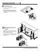
Assembly (continued) 11 A ttaching the Handles □ Attach the handles (DD) to the left and right side cabinet doors by inserting two screws through the doors and turning clockwise into the knobs (DD). Do not strip the screws by overtightening. Q Q DD 12 EE I nstalling the shelves □ Insert eight shelf pins (EE) into the interior of the side panels. Insert the pins parallel to one another to ensure the shelves are level. □ Insert the two shelves (M) onto the shelf pins (EE).
Assembly (continued) 13 I nstalling the firebox □ Insert the firebox into the media console through the back opening. □ Push the firebox forward through the back opening until the metal trim of the firebox in flush with the side panels. □ Once the firebox is in position attach the two mounting brackets included with the firebox by inserting and tightening four screws through the mounting brackets into the firebox and the base panel. □ Do not strip the screws by overtightening.
Service Parts P A N F D M G C H Q P L K L M J E Q B Part Description Quantity Part Number Part Description Quantity Part Number A Top Panel 1 20-01-360 J Right Inside Panel 1 20-01-368 B Base Panel 1 20-01-361 K Front Firebox Support 1 20-01-369 C Media Shelf 1 20-01-362 L Firebox Support 2 20-01-370 D Left Side Panel 1 20-01-363 M Adjustable Shelf 2 20-01-371 E Right Side Panel 1 20-01-364 N Upper Back Panel 1 20-01-372 F Left Upper Inside Pane
Troubleshooting If you have any questions regarding the product, please call Home Depot Customer Service, 1-800-986-3460, 8 a.m. –7 p.m. EST, Monday – Friday, 9 a.m. - 6 p.m., EST, Saturday. Problem Possible Cause Solution The thermostat sensor is broken or disconnected. Unplug the fireplace, remove the panel assembly of the fireplace and check that the thermostat is plugged into the main circuit board. If this does not solve the problem contact customer service for a replacement thermostat sensor.
Questions, problems, missing parts? Before returning to the store, call Home Decorators Collection Customer Service 8 a.m. - 7 p.m., EST, Monday-Friday, 9 a.m. - 6 p.m., EST, Saturday 1-800-986-3460 HOMEDEPOT.COM/HOMEDECORATORS Retain this manual for future use. Manufactured by: GHP Group, Inc. • 6440 W. Howard St.
Artículo Modelo # 269-218-463-Y # 1005228146 GUÍA DE USO Y CUIDADO COLECCIÓN BARDEN: CHIMENEA ELÉCTRICA CON REPISA INSTRUCCIONES IMPORTANTES POR FAVOR, LEA ESTE MANUAL ANTES DE LA INSTALACIÓN Y USO DEL DISPOSITIVO ¡ADVERTENCIA! SI LA INFORMACIÓN EN ESTE MANUAL NO SE SIGUE CON EXACTITUD, PUEDE RESULTAR UN CHOQUE ELÉCTRICO O INCENDIO OCASIONANDO DAÑOS A LA PROPIEDAD, LESIONES PERSONALES O LA MUERTE. INSTALADOR: Deje este manual con el dispositivo. CONSUMIDOR: Conserve este manual para uso futuro.
Tabla de contenido Tabla de contenido . . . . . . . . . . . . . . . . . . . . . . . . . . . . . . . . . . 16 Garantía. . . . . . . . . . . . . . . . . . . . . . . . . . . . . . . . . . . . . . . . . . . 16 Pre-ensamblaje. . . . . . . . . . . . . . . . . . . . . . . . . . . . . . . . . . . . . 17 Planificación del ensamblaje. . . . . . . . . . . . . . . . . . . . . . . . . 17 Herramientas necesarias. . . . . . . . . . . . . . . . . . . . . . . . . . . . 17 Piezas incluidas. . . . . . . . . . . . . . . . . .
Pre-ensamblaje PLANIFICACION DEL ENSAMBLAJE ntes de iniciar el ensamblaje localice las instrucciones y las piezas. Compare todas las piezas con la lista de piezas incluidas y contenido A del embalaje. Asegúrese de tener todas las piezas y de que pueda identificarlas. Siempre es bueno contar con ayuda. Ensámblelo con asistencia de una persona adulta si es posible. Algunas piezas son pesadas y necesitará ayuda. El tiempo de ensamblaje se estima entre 30-60 minutos.
Pre-ensamblaje (continuación) CONTENIDO DEL PAQUETE P A N F D M Q G C H P L L K M J E Q B Pieza Descripción Cantidad Pieza Descripción Cantidad A Panel superior 1 J Panel interior derecho 1 B Panel de base 1 K Soporte superior de caja de fuego 1 C Repisa multimedia 1 L Soporte de caja de fuego 2 D Panel lateral izquierdo 1 M Repisa ajustable 2 E Panel lateral derecho 1 N Panel trasero superior 1 F Panel lateral superior izquierdo 1 P Panel trasero 2 G
Ensamblaje 1 Fijación de la base □ Localice el panel base (B) y colóquelo sobre una superficie suave para proteger el acabado. □ Localice el panel base (B). Fije el panel de inserción (K) al panel de base (B) insertando dos pernos (AA) a través de los conectores y girándolos en el sentido de las agujas del reloj. No pele los tornillos (AA) apretando demasiado.
Ensamblaje (continuación) del panel interior 3 Fijación izquierdo y derecho □ Localice el panel interior izquierdo y derecho (H y J) y fíjelo al panel base (B) insertando cuatro clavijas (BB) en los orificios provistos. □ Inserte dos pernos (AA) a través de los conectores y gírelos en sentido horario. No pele los tornillos (AA) apretando demasiado.
Ensamblaje (continuación) del estante de 5 Colocación medios □ □ BB Fije el panel lateral izquierdo y derecho (D y E) y el estante de medios (C) al ensamblaje del panel base insertando cuatro clavijas (BB) en los orificios provistos. D Inserte seis pernos (AA) a través de los conectores y gírelos en sentido horario. No pele los tornillos (AA) apretando demasiado.
Ensamblaje (continuación) 7 F ijación del panel superior □ □ Ubique el panel superior (A) y colóquelo con cuidado en la parte superior del ensamblaje del estante de medios). Inserte seis pernos (AA) a través de las conexiones y gire en el sentido de las agujas del reloj. No pele los tornillos (AA) apretando demasiado.
Ensamblaje (continuación) 9 Preparando las puertas □ Ubique las dos puertas (Q) y colóquelas sobre una superficie blanda para proteger el acabado. □ Fije las dos bisagras a la puertas (Q) insertando cuatro tornillos de bisagra (HH). Repita este paso para la segunda puerta (Q). No dispare los tornillos de la bisagra (HH) apretando demasiado Qx2 HH HH GG ijación de las puertas a la 10 F chimenea □ Fije las dos puertas (Q) al interior de la repisa apretando los tornillos en la bisagra.
Ensamblaje (continuación) 11 C olocando las manijas □ Fije las manijas (DD) a las puertas del gabinete del lado izquierdo y derecho insertando dos tornillos a través de las puertas y girándolas en el sentido de las agujas del reloj hacia las perillas (DD). No pele los tornillos apretando demasiado. Q Q DD 12 EE I nstalar los estantes □ Inserte ocho pasadores de repisa (EE) en el interior de los paneles laterales.
Ensamblaje (continuación) nstalación de la cámara de 13 Icombustión □ Inserte la caja de fuego en la consola de medios a través de la abertura posterior. □ Empuje la caja de fuego hacia adelante a través de la abertura posterior hasta que el borde metálico de la caja de fuego quede al ras con los paneles laterales.
Piezas de servicio P A N F D M G C H Q P L K L M J E Q B Pieza Descripción Cant. Pieza # Pieza Descripción Cant.
Resolución de fallas Si tiene preguntas respecto al producto, llame a Servicio al Cliente de Home Decorators al 1-800-986-3460, 8 a.m. - 7 p.m., Hora del Este de lunes a viernes, 9 a.m. - 6 p.m., Hora del Este de Sábado Problema Causa posible Solución El sensor del termostato está dañado o desconectado. Desconecte la cámara de combustión, remueva el panel de la cámara de combustión y revise que el termostato esté enchufado en el tablero del circuito principal.
¿Preguntas, problemas o partes faltantes? Antes de regresar a la tienda, llame al servicio de atención al cliente de Home Decorators Collection 8 a.m. - 7 p.m., Hora del Este de lunes a viernes, 9 a.m. - 6 p.m., Hora del Este de Sábado 1-800-986-3460 HOMEDEPOT.COM/HOMEDECORATORS Guarde este manual para futuras referencias. Fabricado por: GHP Group, Inc. • 6440 W. Howard St.