
Instructions / Assembly


8
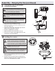
Assembly - Standard Ceiling Mount
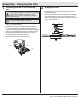
Routing the wiresPreparation for standard mounting
□ Route the wires exiting at the top of the fan-motor
assembly (E) through the canopy ring (HH).
□ Insert the ball/downrod (B) through the canopy (C) and
slide the decorative motor collar cover (D) onto the end
of the ball/downrod (B). Make sure the slots on the
canopy (C) are on top.
□ Route the wires exiting the top of the fan motor
assembly (E) through the downrod as shown.
21
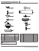
C
A
HH
GG
FF
E
C
D
B
HH
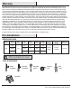
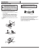
□ Remove the canopy ring (HH) from the canopy (C) by turning
the ring counterclockwise until it unlocks.
□ Remove the mounting bracket (A) from the canopy (C) by
loosening the two canopy screws (FF) located in the “L
shaped” slots.
□ Remove and save the two canopy screws (GG) in the round
holes. This will enable you to remove the mounting bracket
(A).
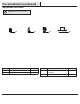
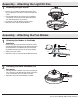
Assembling the fan
□ Loosen, but do not remove, the setscrew (JJ) on the collar
(KK) on top of the fan-motor assembly (E).
□ Install the downrod (B) by inserting it into the motor collar
(KK), and turning it clockwise until it is tight.
□ Re-tighten the setscrew (JJ) on the collar (KK) on top of the
fan motor assembly (E).
3
II
JJ
B
E
KK
NOTE: This fan is equipped with a safety tab (II). Should
the setscrew (JJ) ever become loose while the fan is
running in reverse, the safety tab (II) will engage and stop
the fan from falling.
CAUTION: To ensure wobble-free operation and to avoid
damage to the fan, the downrod (B) and the setscrew
(JJ) must be completely tightened.