Item #296-347 Model #54725 #54727 #54728 #54729 USE AND CARE GUIDE MERCER 52 INCH CEILING FAN Questions, problems, missing parts? Before returning to the store, call Home Decorators Collection Customer Service 8 a.m. - 7 p.m., EST, Monday-Friday, 9 a.m. - 6 p.m., EST Saturday 1-800-986-3460 HOMEDEPOT.
Table of Contents Table of Contents .......................................................... 2 Operation ......................................................................17 Remote Control Operating Instructions ..................................17 Installing the Remote Control Holder ..................................... 17 Reverse Switch Operating Instructions ..................................18 Safety Information ......................................................... 3 Warranty ..............
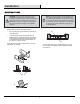
Safety Information 1. To reduce the risk of electric shock, ensure electricity has been turned off at the circuit breaker or fuse box before beginning. 2. All wiring must be in accordance with the National Electrical Code “ANSI/NFPA 70-1999” and local electrical codes. Electrical installation should be performed by a qualified licensed electrician. 3. The outlet box and support structure must be securely mounted and capable of reliably supporting a minimum of 35 lbs (15.9 kg) or less.
Warranty We warrant the fan motor to be free from defects in workmanship and material present at time of shipment from the factory for a period of lifetime after the date of purchase by the original purchaser. We also warrant that all other fan parts, excluding any glass or acrylic blades, to be free from defects in workmanship and material at the time of shipment from the factory for a period of two years after the date of purchase by the original purchaser.
Pre-Installation (continued) HARDWARE INCLUDED NOTE: Hardware shown to actual size unless noted otherwise in the table below.
Pre-Installation (continued) PACKAGE CONTENTS A B C D E F H G J I M K N L Part Description O Quantity Part Description Quantity A Mounting bracket (preassembled) 1 I Blade support plate 4 B Canopy ring (preassembled) 1 J Light kit mounting plate 1 C Canopy 1 K 14 watt LED Light kit 1 D Canopy bottom cover (preassembled) 1 L Glass shade 1 E Hanger ball/downrod assembly 1 M Receiver 1 F Coupling cover 1 N Remote control 1 G Fan motor assembly 1 O Remote c
Pre-Installation (continued) DUAL MOUNTING INSTRUCTIONS This ceiling fan is supplied with two types of hanging assemblies: the standard ceiling installation using the downrod with ball and socket mounting, and the "close-to-ceiling" mounting. The "close-to-ceiling" mounting is recommended in rooms with less than 8 ft. ceilings or in areas where additional space is desired from the floor to the fan blades.
Installation MOUNTING OPTIONS NOTE: You may need a longer downrod to maintain proper blade clearance when installing on a steep, sloped ceiling. The maximum angle allowable is 18° away from horizontal. If the canopy (C) touches the hanger ball/downrod assembly (E), then remove the decorative canopy bottom cover (D) and turn the canopy (C) 180° before attaching the canopy (C) to the mounting bracket (A).
Assembly — Standard Ceiling Mounting 1 2 Preparing the canopy Preparing the motor □ Remove the canopy ring (B) from the canopy (C). □ □ Remove the two non-slotted mounting bracket screws (BB) from the canopy (C), and loosen the slotted mounting bracket screws (BB) on the canopy (C). Remove the cotter pin (GG) and clevis pin (FF), and loosen the two collar setscrews (JJ) from the motor collar.
Assembly — Close-to-Ceiling Mounting 1 2 Preparing the canopy □ Remove the canopy ring (B) from the canopy (C). □ Remove the mounting bracket (A) from the canopy (C) by loosening the four mounting bracket screws (BB) on the top of the canopy (C). □ Remove the two non-slotted mounting bracket screws (BB) and loosen the slotted mounting bracket screws (BB). □ Remove the canopy bottom cover (D) from the canopy (C) by turning the canopy bottom cover (D) counterclockwise.
Assembly — Hanging the Fan 4 Attaching the fan to the electrical box WARNING: To reduce the risk of fire, electric shock or other personal injury, mount the fan only to an outlet box or supporting system marked acceptable for fan support and use the mounting screws provided with the outlet box. □ Pass the 120-volt supply wires through the center hole in the mounting bracket (A).
Assembly — Hanging the Fan (continued) Preparing the receiver and remote control 6 WARNING: To avoid possible electrical shock, be sure electricity is turned off at the main fuse box before wiring. N CAUTION: Do not use with a wall light dimmer switch. M If you feel you do not have enough electrical wiring knowledge or experience, have your fan installed by a licensed electrician.
Assembly — Hanging the Fan (continued) 7 Making the electrical connections WARNING: Check to see that all connections are tight, including ground, and that no bare wire is visible at the wire nuts, except for the ground wire. CAUTION: Do not use with a wall light dimmer switch. □ If your outlet box (PP) has a ground wire (green or bare copper) connect it to the fan ground wires; otherwise connect the hanger ball/downrod assembly (E) ground wire to the mounting bracket (A).
Assembly — Hanging the Fan (continued) 8a 8b Standard ceiling mounting WARNING: Locking slots of the canopy (C) are provided only as an aid to mounting. Do not leave the fan assembly unattended until all four canopy screws (BB) are engaged and firmly tightened. WARNING: Make sure the tab on the mounting bracket (A) properly sits in the groove in the hanger ball (E) before attaching the canopy (C) to the mounting bracket (A) by turning the canopy (C) until it drops into place.
Assembly — Attaching the Fan Blades 9 Attaching the Fan Blades WARNING: To reduce the risk of personal injury, do not bend the blades (H) while installing, balancing the blades (H), or cleaning the fan. WARNING: Remove the three rubber packing mounts (UU) from the fan motor assembly (G) and discard prior to attaching the blades (H). UU WARNING: Do not insert foreign objects between rotating fan blades (H). □ Insert the blade (H) through the slot in the housing.
Assembly — Installing the Light Kit 10 Attaching the light kit mounting plate to the mounting ring □ Remove one of the three light kit mounting plate screws (LL) from the mounting ring (VV) and loosen the other two screws. (Do not remove.) □ Place the key holes in the light kit mounting plate (J) over the two screws (LL) previously loosened from the mounting ring (VV). Turn the light kit mounting plate (J) until the light kit mounting plate (J) locks in place at the narrow section of the key holes.
Operation REMOTE CONTROL OPERATING INSTRUCTIONS □ Install the 12V MN21/A23 battery (NN) (included) into the remote control (N). To prevent damage to the remote control (N), remove the battery if not used for long periods. □ Restore power to the ceiling fan and test for proper operation. N HI , MED, LOW buttons: set the fan speed. OFF button: turns the fan off. NN button: turns the light on or off and also controls the brightness setting. Press and release this button to turn the light on or off.
Operation (continued) REVERSE SWITCH OPERATING INSTRUCTIONS The reverse switch is located on the top of the motor housing. Slide the switch to the left for warm weather operation. Slide the switch to the right for cool weather operation. NOTE: Wait for the fan to stop before reversing the direction of the blade rotation. Warm weather - (Counterclockwise Direction) A downward air flow creates a cooling effect. This allows you to set your air conditioner on a warmer setting without affecting your comfort.
Troubleshooting WARNING: Make sure the power is off at the electrical panel box before you attempt any repairs. Refer to step 7 “Making the electrical connections” on page 13. Problem The fan will not start. The fan sounds noisy. The remote control is not working. Solution □ Check the main and branch circuit fuses or breakers. □ Check the line wire connections to the fan and switch wire connections in the switch housing.
Service Parts A I B C D J E AA HH BB II CC JJ K F DD L G EE KK LL MM FF M NN GG N H OO O Part Description Part Description A Mounting bracket (preassembled) BB Canopy mounting bracket screw with lock washer B Canopy ring (preassembled) C Canopy CC D Canopy bottom cover (preassembled) DD Remote control holder mounting screw E Hanger ball/downrod assembly EE Remote control holder plug (preassembled) F Coupling cover FF Clevis pin (preassembled) G Fan motor assembl
Questions, problems, missing parts? Before returning to the store, call Home Decorators Collection Customer Service 8 a.m. - 7 p.m., EST, Monday-Friday, 9 a.m. - 6 p.m., EST Saturday 1-800-986-3460 HOMEDEPOT.COM/HOMEDECORATORS Retain this manual for future use.
Artículo Núm.296-347 Modelo Núm.54725 54727 54728 54729 GUÍA DE USO Y MANTENIMIENTO VENTILADOR DE TECHO MERCER, DE 1,32 m ¿Preguntas, problemas o piezas faltantes? Antes de regresar a la tienda, llama al Servicio al Cliente de Home Decorators Collection de lunes a viernes entre De lunes a viernes, entre 8:00 a.m. y 7:00 p.m. (Hora Estándar del Este), y los sábados de 9:00 a.m. a 6:00 p.m. (Hora Estándar del Este). 1-800-986-3460 HOMEDEPOT.
Índice Índice .............................................................................. 2 Funcionamiento ........................................................... 17 Instrucciones de control remoto de funcionamient..................17 Instalando el sosten del control remoto................................... 17 Instrucciones de funcionamiento del interruptor de reversa......18 Información de Seguridad............................................. 3 Garantía ..........................................
Información de Seguridad 1. Para disminuir el riesgo de descarga eléctrica, asegúrate de que la electricidad ha sido apagada en el cortacircuitos o la caja de fusibles antes de comenzar la instalación. 2. Todo el cableado debe cumplir con el Código Nacional de Electricidad "ANSI/NFPA 70-1999" y con los códigos locales de electricidad. La instalación eléctrica debe ser hecha por un electricista certificado y calificado. 3.
Garantía Le garantizamos de por vida, a partir de la fecha en que el comprador original lo adquiere, que el motor del ventilador no presenta defectos de fabricación ni de material al momento en que es enviado desde la fábrica.
Pre-Instalación (continuación) HERRAJES INCLUIDOS NOTA: Se muestra el tamaño real de los herrajes, excepto cuando se especifiquelo contrario en la tabla a continuación.
Pre-Instalación (continuación) CONTENIDO DEL PAQUETE A B C D E F H G J I M K N L Pieza Descripción O Cantidad Part A Soporte de montaje (preensamblado) 1 I Placa de soporte para las aspa 4 B Anillo de lacubierta (preensamblado) 1 J Placa de montaje del kit de luces 1 C Cubierta 1 K Kit de luces LED de 14W 1 D Tapa del fondo de la cubierta (preensamblado) 1 L Pantalla de vidrio 1 E Ensamblado de tubo bajante/bola de soporte 1 M Receptor 1 F Cubierta del acoplamiento
Preinstalación (continuación) INSTRUCCIONES DE MONTAJE DOBLE Este ventilador de techo viene con dos tipos de ensamblajes de soporte: la instalación de techo estándar con tubo bajante y bola y soporte de montaje; y el montaje “cerca del techo”. El montaje “cerca del techo” se recomienda en habitaciones con techos de menos de 2.44 metros de altura o en áreas donde se desee espacio adicional entre el piso y las aspas del ventilador.
Instalación OPCIONES DE MONTAJE ADVERTENCIA: Para disminuir el riesgo de incendio, descarga eléctrica o lesiones personales, monta el ventilador sobre una caja eléctrica marcada como “aprobada como soporte de ventilador” y usa los tornillos de montaje que vienen con la misma. Las cajas eléctricas utilizadas comúnmente para el soporte de artículos de iluminación pueden no servir como soporte de ventilador, y tal vez deban reemplazarse. En caso de duda, consulta a un electricista calificado.
Ensamblaje — Montaje estándar en techo 1 2 Cómo preparar la cubierta Cómo preparar el motor □ Retire el anillo de cubierta (B) de la cubierta (C). □ □ Quita los dos tornillos sin ranura del soporte de montaje (BB) de la cubierta (C) y afloja los tornillos ranurados del soporte de montaje (BB) en la cubierta (C). Retira el pasador tipo horquilla (GG) y pasador de chaveta (FF), y afloja los dos tornillos de ajuste de collarín (JJ) del collarín del motor.
Ensamblaje — Montaje "cerca del techo" 1 2 Cómo preparar la cubierta □ Retire el anillo de cubierta (B) de la cubierta (C). □ Retira el soporte de montaje (A) de la cubierta (C) aflojando los cuatro tornillos del soporte de montaje (BB) en la parte superior de la cubierta (C). □ Quita los dos tornillos sin ranura del soporte de montaje (BB) y afloja los tornillos ranurados del soporte de montaje (BB).
Ensamblaje — Cómo colgar el ventilador 4 Cómo fijar el ventilador a la caja eléctrica ADVERTENCIA: Para reducir el riesgo de incendio, descarga eléctrica o lesiones físicas, sólo instala el ventilador en una caja eléctrica o sistema de soporte aprobados para ventiladores y usa los tornillos de montaje que vienen con la caja eléctrica. □ Pasa los cables de suministro de 120 V a través del orificio central en el soporte de montaje (A).
Ensamblado — Cómo Colgar el Ventilador (continuación) 6 Cómo preparar el receptor y el control remoto ADVERTENCIA: Para evitar una posible descarga eléctrica, asegúrate de que la electricidad esté apagada de la caja de fusibles principal antes de realizar el cableado. N PRECAUCIÓN: No usar con un interruptor de pared regulador de intensidad. M Si crees que no tienes suficiente experiencia o conocimientos sobre cableado eléctrico, contrata a un electricista con licencia para que instale el ventilador.
Ensamblado — Cómo Colgar el Ventilador (continuación) ADVERTENCIA: Verifica que todas las conexiones estén bien ajustadas, incluida la conexión a tierra, y que no haya ningún cable pelado visible en las tuercas para cable (excepto el de tierra). PRECAUCIÓN: No usar con un interruptor de pared regulador de intensidad.
Ensamblaje — Cómo colgar el ventilador (continuación) 8a 8b Montaje estándar en techo ADVERTENCIA: Asegúrate de que la pestaña del soporte de montaje (A) encaje bien dentro de la ranura de la bola de soporte (E) antes de sujetar la cubierta (C) al soporte de montaje (A), girando la cubierta (C) hasta que encaje en su lugar. ADVERTENCIA: Las ranuras de cierre de la cubierta (C) sólo sirven de ayuda durante el montaje.
Ensamblaje — Cómo Montar las Aspas del Ventilador 9 Cómo Montar las Aspas del Ventilador ADVERTENCIA: Para reducir el riesgo de lesiones personales, no doblar los aspas (H) durante la instalación, compensación de las aspas (H) o limpieza del ventilador. ADVERTENCIA: Retira los tres soportes de embalaje de goma (UU) del ensamblaje del motor del ventilador (G) y deséchalos antes de montar los aspas (H). UU ADVERTENCIA: No insertes objetos extraños entre las aspas (H) en funcionamiento.
Ensamblaje — Cómo Instalar el Kit de Luces 10 Cómo instalar la placa de montaje del kit de luces en el anillo de montaje □ Retira 1 de los 3 tornillos del placa de montaje del kit de luces (LL) del anillo de montaje (VV) y afloja los otros 2 tornillos.
Funcionamiento INSTRUCCIONES DE OPERACIÓN DEL CONTROL REMOTO □ Instala una batería MN21/A23 de 12V (NN) (incluida) en el control remoto (N). Para prevenir daños al control remoto (N), sacala batería si no va a usarse por largo tiempo. □ Conecte la eléctricidad a el ventilador y confirme que opera debidamente. N Los bottones HI, MED, LOW: establece la velocidad del ventilador. NN Boton OFF : apaga el ventilador.
Funcionamiento (continuación) INSTRUCCIONES DE FUNCIONAMIENTO DEL INTERRUPTOR DE REVERSA El Interruptor de Reversa está ubicado en la superficie de la carcasa del motor. Desliza el interruptor hacia a la izquierda para funcionamiento en clima cálido. Desliza el interruptor hacia a la derecha para funcionamiento en clima fresco. NOTA: Espera a que se detenga el ventilador antes de invertir la dirección de giro de las aspas.
Solución de Problemas ADVERTENCIA: Asegúrate de que la electricidad esté cortada en el panel de electricidad antes de intentar hacer reparaciones. Consulta el paso 7 “Cómo Hacer las Conexiones Eléctricas” en la página 13. Problema El ventilador no enciende. El ventilador hace ruido. El control remoto no funciona. Solución □ Verifica fusibles o disyuntores principales y secundarios.
Piezas de Repuesto A I B C D J E AA HH BB II CC JJ K F DD L G EE KK LL MM FF M NN GG N H OO O Pieza Descripción Pieza Descripción A Soporte de montaje (preensamblado) B Anillo de lacubierta (preensamblado) BB Tornillo del soporte de montaje de la cubierta con C Cubierta CC D Tapa del fondo de la cubierta (preensamblado) DD Tornillo de montaje del soporte del control remoto E Ensamblado de tubo bajante/bola de soporte EE Tapón del soporte del control remoto (preensambla
¿Preguntas, problemas o piezas faltantes? Antes de regresar a la tienda, llama al Servicio al Cliente de Home Decorators Collection de lunes a viernes entre De lunes a viernes, entre 8:00 a.m. y 7:00 p.m. (Hora Estándar del Este), y los sábados de 9:00 a.m. a 6:00 p.m. (Hora Estándar del Este). 1-800-986-3460 HOMEDEPOT.COM/HOMEDECORATORS Conserva este manual para referencias futuras.