
Installation Guide


Installation Instructions
Luxury Vinyl Plank and Tile Flooring
For Assistance, Call: 1-800-986-3460
www.homedepot.com/homedecorators
Product Description
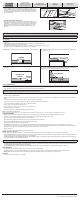
4.2 mm thick 6 in. x 36 in., 8 in. x 48 in.,
6 in. x 48 in. planks and 12 in. x 24 in. tiles
Grade Levels
Above Grade / On Grade
Below Grade
Installation Method
Floating - Drop and Lock
HOMEDEPOT.COM/HOMEDECORATORS
Please contact 1-800-986-3460 for further assistance.
CAUTION: ASBESTOS IN EXISTING FLOOR: This product does not contain asbestos. Existing installed resilient ooring and asphaltic adhesive may contain asbestos llers or crystalline silica. Do not sand, dry sweep, dry
scrape, drill, saw, bead-blast, or mechanically chip or pulverize existing resilient ooring, backing, lining felt, asphaltic “cutback” adhesive or other adhesive. See “Recommended Work Practices for Removal of Resilient Floor
Coverings” (rfci.com) for detailed information and instructions on removing all resilient covering structures.
CAUTION: DO NOT INSTALL IN all exterior installations, seasonal porches, boats, campers, RV's, sunrooms, solariums, non-temperature controlled rooms or homes.
Safety and Health Precautions
Power tools can be dangerous. Operate in strict accordance to manufacturer’s operating instructions and safety precautions. Unsafe and improper use can cause serious injuries. Avoid inhalation and exposures to airborne particles
by mechanical means and by wearing personal protective equipment. Wear appropriate personal protective equipment (PPE) which includes NIOSH or OSHA approve dust masks, safety goggles and work gloves.
Warranty
This ooring product comes with a manufacturer Limited Wear Warranty. The warranty applies to the original purchaser of the ooring. It warrants the original purchaser that the nish surface will not wear through for the duration of
the stated warranty from the date of purchase. Contact our Customer Service Team at 1-800-986-3460 to request a written copy which provides detailed terms of coverage and limitations.
Pre-Installation
OWNER/INSTALLER RESPONSIBILITY
The owner is advised to be at home during the installation for consultation/direction. The owner and installer
should discuss installation and layout to maximize satisfaction. If this is not possible, consultation should be done
prior to installation. The owner/installer assumes all responsibility for product quality of completed installation.
PERFORM PRE-INSTALL INSPECTION. FOR CLAIMS PURPOSES, YOU ARE ALLOWED TO OPEN UP TO 4 BOXES FOR
PRODUCT INSPECTION. DO NOT OPEN ALL THE BOXES. OPENING ALL THE BOXES CONSTITUTES YOUR ACCEPTANCE
OF THE PRODUCT. INSPECT ALL THE TILES IN THESE 4 BOXES CAREFULLY. EXAMINE FLOORING FOR COLOR, FINISH
AND QUALITY. IF YOU DISCOVER THAT PRODUCTS ARE DEFECTIVE, OR IF MATERIAL IS QUESTIONABLE, YOU SHOULD
CONTACT THE RETAILER. IF YOU ARE SATISFIED, PROCEED WITH INSTALLATION.
Prior to installation, rack up planks/tiles from several boxes to ensure uniform distribution of colors, shades and
characters in the installed ooring. Planks/tiles having similar widths should be placed together in the same row
to minimize gaps between boards.
Purchase ooring to be installed in one large area at the same time. Product purchased at a later time than the
rst purchase may vary beyond your expectations.
Accessories, trims and moldings are manufactured to coordinate with the varied appearances of the oor planks/
tiles. Any exact matches are coincidental. Non-matching accessories are not defective products.
This product is manufactured according to strict quality standards. In the event that defects are discovered in the
eld, the industry standards permit a defect tolerance not to exceed 5%. Order an additional 10% extra for cutting
wastage and grading allowances (more for diagonal installations).
During installation, inspect the planks/tiles continuously. Defects that can be seen from a standing position
should be cut off or held out. Installing defective planks/tiles implies acceptance.
Clicking noises are the result of interactions among ooring, joists and suboors when they move. Sometimes,
it is impossible to eliminate them completely and minor clicking noises are to be accepted as normal ooring
phenomenon.
IMPORTANT: With square edge products, some ledging can be visible up to a .15 mm variance.
To assure the warranty is not inadvertently voided, before proceeding with any activity that is not covered in this
manual, please contact our Customer Support Team at 1-800-986-3460.
CONCRETE SUBFLOOR REQUIREMENTS
Concrete suboors must:
□ Have minimum rated strength of 3000 psi.
□ Be level to within 3/16 in. in a 10 ft. span; no bumps or low spots. High spots can be removed by grinding;
depressions can be lled with patching compound formulated for use in oor installation. Suboors should
not slope more than 1 in. per 6 ft.
□ Be clean; no construction debris, soil, mud and any other objects on or adhering to the oor; if necessary,
scrape and sweep away before the installation; no protrusions of nails, debris, metals should remain.
□ New concrete slab must cure for at least 90 days. It must have a minimum 10 mil polyethylene sheet
between the ground and the concrete.
□ Be free from moisture related conditions which can damage the installed ooring.
CONCRETE MOISTURE
Test all concrete suboors for moisture content and document the results with a photo. For full warranty
coverage, we recommend documenting your test results with a photo. Visual checks are not reliable.
Perform tests at locations around exterior doorways, near walls containing plumbing, near foundation walls
and in the center of the room. Minimum sample size is 3 samples per 1000 sq. ft. of area and one test for every
additional 1000 sq. ft. thereafter.
Moisture content should meet one of the following criteria:
□ 4% max. when tested using Tramex Concrete Moisture Encounter over bare concrete with no adhesive or
sealer.
□ Less than 8 pounds per 1000 sq. ft. per 24 hours when using Calcium Chloride test (ASTM F1869).
□ 85% max. when using Relative Humidity Testing (ASTM F2170).
NOTE: Concrete moisture content may be acceptable the time of the test. These tests do not guarantee a
perpetual “dry” concrete slab. The concrete slab moisture content can vary at other times of the year. We are
not responsible for moisture-related damage to installed ooring.
WOOD SUBFLOOR REQUIREMENTS
The suboor must be clean; no presence of construction debris, soil, mud and any other objects on or adhering
to the oor; no protrusions of nails, debris, or metals should remain. If necessary, scrape and sweep the suboor
before the installation.
The suboor must be structurally sound and stable; no movements or squeaks; no loose panels or loose nails; no
signs of ply de-lamination or other damages. Repair all shortcomings before installation.
The suboor must be at; no visible bumps or low spots; the suboor should be at to within 3/16 in. in 10 ft.
span. Test for moisture using a reliable pin type meter. Perform tests at locations around exterior doorways, near
foundation walls, near walls containing plumbing lines and in the center of the room. Moisture levels should not
exceed 12%.
PLYWOOD OR ORIENTED STRAND BOARD (OSB) SPECIFICATIONS
On truss/joist spacing of 16 in. (406 mm) O/C or less, the industry standard for single-panel subooring is a
minimum 5/8 in. (19/32 in., 15.1 mm) CD Exposure 1 plywood suboor panels (CD Exposure 1) or 23/32 in. OSB
Exposure 1 suboor panels, 4 ft. x 8 ft. sheets. Expansion gap between panels should be 1/8 in. (3 mm). If panels
are not tongued and grooved and there is not sufcient spacing or is inadequate, cut in the required spacing with
a circular saw. Do not cut in expansion space on tongue and groove panels.
PARTICLE BOARD OR FIBER BOARD
Only for oating installation. Product has to be sound and stable with no visible signs of moisture-related
conditions.
EXISTING FLOORS
Installation over existing oor requires the installer to consider potential issues related to moisture damage,
adhesive failure and fastener failure. Contact the adhesive and fastener manufacturers respectively for their
specic instructions, recommendations and requirements.
Acceptable oor coverings include: Solid hardwood (smooth, securely fastened and within acceptable moisture
levels), linoleum (one layer only), terrazzo, ceramic, and stone tile. Tiled oors with grout lines will require a
cementitious leveling compound to ll any grout lines, voids, or cracks.
Unacceptable oor coverings include: Carpet (any type), foam underlayment, cushioned-back vinyl, rubber, cork,
laminates, free-oating oors, and wooden oors over concrete.
JOB SITE CONDITION
Prior to installation, the installer must ensure that at the time of installation, the job site conditions including
suboor/substrate, ambient temperature and relative humidity, and all impacting variables will not negatively
affect the oor. The manufacturer will decline responsibility for damages associated with improper installation
or poor site conditions.
STORAGE AND CONDITIONS
Acclimate the ooring a minimum of 24 hours before installation in the area it is to be installed. Conditions
between 65°F and 85°F (18°C and 29°C) are required before, during and after installation. Cartons should be
evenly stacked no more than ve high on a at surface and away from any heating/cooling ducts or direct
sunlight.
EXISTING HOME
An existing home should have a consistent room temperature between 65°F and 85°F (18°C and 29°C) and
relative humidity (RH) of 35%-85%. Continual deviation from these conditions will affect the dimensions of
ooring. When using a heater during winter months, humidity may be much lower than the acceptable range.
During the warmer months, maintain humidity levels using an air conditioner, dehumidier, or by turning on your
heating system periodically.
NEW CONSTRUCTION OR REMODEL
All work involving water, such as pouring basement concrete oors, drywall and plasterwork, plumbing,
etc. must be completed well in advance of the oor delivery. Ensure that the building is enclosed. Where
building codes allow, permanent heating and/or air conditioning systems should be operating at least two
weeks preceding installation and should be maintained during and after installation. If it is not possible for
the permanent heating and/or air conditioning system to be operating before, during and after installation,
a temporary heating and/or dehumidication system that simulates normal living (occupied) conditions
can enable the installation to proceed until the permanent heating and/or air conditioning system is fully
operational. Your job site should have a consistent temperature between 65°F and 85°F (18°C and 29°C) and
relative humidity (RH) of 35%-85% which should be maintained continuously thereafter.
RECOMMENDED INSTALLATION AREA
Do not install vinyl planks/tiles over carpet or any foam underlayment. This product is not suitable for any
outside use, sunrooms/solariums, saunas, seasonal porches, camping trailers, boats, RV’s or rooms that have
a potential of ooding. Do not install in rooms or homes that are not temperature controlled. Exposure to long
term direct sunlight can cause damage to your oor. Failure to properly shade or UV tint windows can discolor,
fade, or buckle vinyl planks/tiles. Use window treatments or UV tinting on windows. Installation of luxury vinyl
ooring on stairways and landings requires the glue-down method using an approved adhesive and moldings.
Do not glue, nail, screw or fasten to substrate. Install cabinetry, island and peninsula counters, vanities, tubs,
and showers rst. Then install vinyl planks/tiles around them. Please contact our Customer Support Team at
1-800-986-3460 with any questions.
BASEMENTS AND CRAWL SPACES
Concrete slab or ground must be dry. Ensure that crawl spaces have open vents year round to ensure proper air
circulation and prevent moisture build up. The ground in the crawl spaces must be completely covered using 6
mil black polyethylene. Crawl space clearance between the earth and underside of joists should be no less than
18 in. and the perimeter vent area should be equal to 1.5% of the total square footage of the crawl space or as
mandated by code.
RADIANT HEATED SUBFLOOR
This product can be installed over radiant heat concrete suboors. The radiant heating system must be cast
1/2 in. below the surface of the concrete slab and should be operating at least 2 weeks before installation. Set
the temperature of the radiant heating system to 68°F 48 hours before, during, and 72 hours after installation.
You may gradually raise the temperature starting 72 hours after installation. The nished oor surface must
not exceed 85°F (29°C) for the life of the oor. Because radiant heat creates a dry heat that can lower interior
humidity levels, it may be necessary to add a humidier to maintain the humidity level between 30-85% to
prevent damage to the vinyl oor. Consult with the radiant heat system manufacturer to ensure that the system
is compatible with vinyl ooring.
MOISTURE BARRIER/UNDERLAYMENT PADDING
CONCRETE SUBFLOOR
When installing over a crawl space or concrete slab, it may be necessary to use a moisture barrier to prevent
moisture migration. A plastic lm with a minimum thickness of 6 mil should be placed with a 4 – 6 in. (101.6 –
152 mm) overlapped seam, and taped with a suitable tape.
EXPANSION GAP
A required gap width of 1/4 in. is required around the perimeter of the oor and between the oor and all
vertical obstructions. Do not place permanently mounted structures such as kitchen counters/cabinets on the
installed oor.
TRANSITION MOLDING
For oating installation, transition T-molding is required in the following cases: oors spanning greater than 30
ft. in width and 50 ft. in length; doorways and archways less than 4 ft. wide.
TOOLS AND MATERIALS BASICS
Tape measure • Moisture meter (wood, concrete or both) • Utility knife & straight edge • Shears for cutting
around irregular shaped objects (pipes) • 6 mm (1/4 in.) spacers • Pencil • Soft faced hammer (to gently tap
the scrap tapper) • Eye protection • Broom • Small hand roller (seam roller) • Square ruler • Chalk line • Scrap
tapper*
*Scrap tapper: A tapping section cut across the width approximately 6 in. in length then split in the length
direction to provide a tongue and groove “scrap tapper.” This provides equal contact when tapping along the
length joint as noted in the Installation section.
Helpful Pointers
GENERAL TIPS
□ Make sure your work area is well lit. Good visibility ensures that color is consistent and that visually defective planks/tiles are detected and removed.
□ The minimum length of the rst and last plank/tile is 8 in.. If the last plank/tile will be less than 8 in., adjust the length of the rst plank/tile. The remainder of the last plank/tile can be used as a starter board on the following
rows.
□ Using a shorter piece at undercut door jams will help when tting ooring in place.
IMPORTANT: Never hit the ooring directly with a tapping block and be careful not to fracture ooring edges.
□ For plank installation, we recommend staggering the end joints a minimum of 6 inches.
□ For tile installation, we recommend staggering the end joints a minimum of 3 inches.
NOTE: Do not install four corners together, as this will not provide a stable installation.
CUTTING THE LAST ROW TO WIDTH
□ Most often the entire length of the last row will need to be cut so that it is narrow enough to t the remaining space.
□ Measure the distance between the oor face edge (exclude the tongue) to the wall. Subtract 1/4 in. from this measurement for expansion gap. Draw a line. Cut through the line. Discard the excess piece. Proceed with the
installation.
Preparing for Installation
□ Ensure suboors are clean.
□ Lay out several cartons. Randomly rack the ooring planks/tiles to ensure good color and shade mixture
and end joint spacing. Minimum end stagger is 8 in. Inspect plank/tile quality and grading.
□ Lay out trim moldings in advance and nd ooring pieces whose shade closely matches. Set these aside
for future use.
□ Remove the existing base, shoe molding or threshold carefully. They can be used to cover the 1/4 in.
expansion gap left around the edge of the room.
□ Undercut doors and casings using a handsaw laid at on a piece of scrap ooring. Never undercut metal
door casings.
8
Installation
1. INSTALLING THE FIRST ROW
a. First, lay a row of loose planks/tiles (i.e. without securing them to each other; Figure 1.1) to
determine if you need to adjust the length of the rst plank/tile to avoid a small piece (less than 8 in.)
on the opposite wall from where you started. Alternatively, measure the length of the room and divide
by the length of one plank/tile. If the remainder is less than 8 in., calculate 1/2 of the remainder and
trim this amount off the rst plank/tile. The last plank/tile should be the same length as the rst one.
To cut a plank/tile, simply measure and mark the plank/tile. Then, use a straight edge and utility knife
to score and snap.
b. Installation should start in a corner (left hand) and proceed from the wall with the groove facing the
wall (Figure 1.2). Allow a minimum gap of 1/4 in. (6 mm) for suboor movement or product expansion,
which should be covered by molding. Set 1/4 in. spacers to create the required expansion space.
c. Install the rst row in a straight line using a vinyl seam roller to properly secure the end joints
allowing 1/4 in. expansion space next to all walls and vertical surfaces. See Figure 1.4. This is to
allow movement within the structure. DO NOT USE A MALLET OR HAMMER TO INSTALL THE END
JOINT.
d. Stagger the rows so that the short-edge seams are not aligned in a straight, uniform manner. Refer to
the “PREPARING FOR INSTALLATION” section for recommended installation patterns.
1.1
1.2
1.3
1/4 in. (6 mm)
TONGUE
GROOVE
1.4
2. INSTALLING THE SECOND AND REMAINING ROWS
a. Start the second row with the plank/tile cut half the length, or for desired pattern; measure and mark
the plank/tile. Then, use a straight edge and utility knife to score and snap the plank/tile.
b. Attach the rst plank/tile of the second row by connecting the long side to the rst row (Figure 2.1).
Maintain your 1/4 in. expansion gap. Then, attach the second plank/tile by connecting the long side
to the rst row, angling the plank/tile approximately 4 in. - 6 in. up to avoid damage to the proles
on the end joints, and sliding it up to the short end of the rst piece (groove to tongue). Then, drop
and lock (Figure 2.2). To ensure a tight t, use a seam roller on the short seams only, then use a
soft-faced hammer to gently tap the scrap tapper in order to properly secure the length of the joint.
(Figure 2.3).
c. When cutting a plank/tile to start a row, you will need to cut off the end with the groove. The
remaining piece can then be used on the opposite side of the room, at the end of that row (if layout
permits; Figure 2.4). Refer to Figure 2.5 for a close-up of the end-joint locking mechanism.
(CONTINUED)
2.1
2.2
2.3
2.4 2.5
END JOINTS