XXX XXX/85798/23DE9448-NB04 XXX XXX/85521/23DE9448-NC01 XXX XXX/85804/23DE9448-NE01 XXX XXX/85811/23DE9448-PT85 USE AND CARE GUIDE CHARLES MILL ELECTRIC FIREPLACE Questions, problems, missing parts? Before returning to the store, call Home Decorators Collection Customer Service 8 a.m. - 6 p.m., EST, Monday - Friday 1-800-986-3640 HOMEDEPOT.COM/HOMEDECORATORS THANK YOU We appreciate the trust and confidence you have placed in Home Decorators through the purchase of this electric fireplace.
Table of Contents Maximum Load Warning................................................................. 2 Safety Information............................................................................. 3 Warranty................................................................................................ 4 Pre-Assembly....................................................................................... 5 Hardware Included ................................................... 5 Product Specifications.....
Safety Information Important Safety Instructions Please read and understand this entire manual before attempting to assemble, operate or install the product. If you have any questions regarding the product, please call customer service at 1-800-986-3460, 8 a.m.-6 p.m., EST, Monday-Friday. When using electrical appliances, always follow basic precautions to reducetheriskoffire,electricalshock,andinjurytopersons,including the following: WARNING: Under no circumstances should this fireplace be modified.
Warranty 1Year LimitedWarranty:The manufacturer warrants this product to be free from manufacturing and material defects for a period of one year from date of purchase, subject to the following conditions and limitations: 1. Install and operate this Electric Fireplace in accordance with the installation and operating instructions furnished with the product at all times. Any unauthorized repair, alteration, willful abuse, accident, or misuse of the product shall nullify this warranty. 2.
Pre-Assembly A PH-PCBBLK001 HARDWARE INCLUDED Plastic Connector Block 19PCS Ø4*12mm BOLT AA BB CC DD EE L-1 II JJ Part AA BB CC DD EE FF GG HH II JJ KK LL MM NN ZZ KK 16PCS FF GG HH L-2 LL MM Description 2 Hole Plastic Connector Block 3 Hole Plastic Connector Block Short Flathead Screw Bolt Floor Glide (Pre-attached) Knob (with Screw) Long Flathead Screw Metal Plate (Pre-attached) Small Plastic Connector Block Long Washerhead Screw Shelf Pin Hinge Wood Dowel Short Washerhead Screw Touc
Pre-Assembly (continued) PACKAGE CONTENTS NOTE: All panels are labeled left and right as viewed from the front of unit.
Assembly 1 2 Preparing the Partitions Preparing the Partitions Attach 2 Hole Plastic Connector Block (AA) to the Left Partition (C) using Bolts (DD). Repeat the process for the Right Partition (E). Attach the Small Plastic Connector Block (II) to the Right Partition (E) using Short Flathead Screws (CC). Repeat the process for the Left Partition (C).
Assembly (continued) 4 5 Preparing the Middle Front Panel Attaching the Middle Front Panel Insert the Wood Dowels (MM) into the pre-drilled holes on the ends of the Middle Front Panel (F). Connect the Left Front Panel (B) to the Middle Front Panel (F) with the Long Washerhead Screws (JJ). Repeat for the Right Front Panel (D). Screw the Bolts (DD) through the 2 Hole Plastic Connector Blocks (AA) into the Middle Front Panel (F) and tighten.
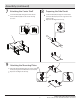
Assembly (continued) 7 8 Attaching the Center Shelf Screw the Bolts (DD) through the 2 Hole Plastic Connector Blocks (AA) into the Center Shelf (J) to secure. Preparing the Side Panels Screw the Bolt (DD) through the 2 Hole Plastic Connector Block (AA) onto the edge of the Left Side Panel (H). Repeat for the Right Side Panel (I). AA DD DD AA J H I 9 H Attaching the Mounting Plates NN Attach the Hinge Mounting Plate (L-1) to the Left Side Panel (H) using the Short Washerhead Screw (NN).
Assembly (continued) 10 Attaching the Side Panels 11 Attaching the Base Assembly Attach the Left Side Panel (H) and the Right Side Panel (I) to the assembly from the step 7. Secure using the Bolts (DD) through the 2 Hole Plastic Connector Blocks (AA). Insert the Wood Dowels (MM) into the pre-drilled holes on the completed assembly from Step 10. Using the Long Flathead Screw (GG) attach the Base Assembly (A) to the bottom of the completed assembly from Step 10.
Assembly (continued) 13 Attaching the Divider 14 Attaching the Top Assembly Insert Wood Dowels (MM) into the pre-drilled holes in the Divider (K). Secure the Divider (K) to the Center Shelf (J) with the Large Flathead Screw (GG). K Attach theTop Assembly (G) to the completed assembly from Step 13. Secure using the Bolts (DD) through the 2 Hole Plastic Connector Blocks (AA).
Assembly (continued) 16 Preparing the Doors 17 Attaching the Knobs Remove the preassembled screws from the Knobs (FF), then attach the Knob (FF) to the Left Door (N) and Right Door (O) with the screws. Attach the Hinges (L-2) to the Right Door (O) using the Short Washerhead Screw (NN). Repeat for the Left Door (N). FF N N O NN O L-2 18 Installing the Doors Attach the Left Door (N) and the Right Door (O) by sliding the Hinges (L-2) onto the Hinge Brackets (L-1).
Assembly (continued) the Fireplace Insert into 19 Installing the Adjustable Shelves 20 Installing the Mantel Assembly Choose desired height of the Adjustable Shelf (P) and place the four Shelf Pins (KK) in the corresponding holes. Insert the Adjustable Shelf (P) on top of the Shelf Pins (KK). Lift the Fireplace Insert (T) carefully into the back of the unit and center in the fireplace insert opening. Do not drag the fireplace insert across the Base Assembly (A) as it may scratch your unit.
Assembly (continued) 22 Preparing the Corner Extension 23 AssemblingtheCornerExtension Place the Corner Extension (R) face down on a scratch free surface. Attach 2 Plastic Connector Blocks (AA) to the Corner Brace (S) using Bolts (DD). Repeat this process for the Corner Extension (R). Attach the Corner Brace (S) to the Corner Extension (R) by inserting Bolts (DD) through the holes in the 2 Hole Plastic Connector Block (AA) and tighten.
Operation NOTE: The control panel can be accessed at the upper-right corner of the insert. When a function is changed from the control panel or remote control there will be a corresponding indicator (see Figure 1) on the upper-right of the projection screen. The indicator shows the function changed and the level selected by the control panel or remote control.When the function is turned off, the corresponding indicator will flash several times and then fade off. Fig .
Operation (continued) 7 ReplacingtheRemoteControlBatteries 8 Disposing of Used Batteries The battery may contain hazardous substances that could endanger the environment and human health. When the remote control stops operating or its range seems reduced, it is time to replace the batteries with new ones. On the back end of the remote, press and slide the battery door open and remove the old batteries.
FCC/IC Information This equipment has been tested and found to comply with the limits for Class B digital device, pursuant to part 15 of the FCC Rules. These limits are designed to provide reasonable protection against harmful interference in a residential installation.
Troubleshooting PROBLEM POSSIBLE CAUSE CORRECTIVE ACTION The display shows “E1”. The thermostat sensor is broken or disconnected. Unplug the fireplace, remove the back panel of the fireplace and check that the thermostat is plugged into the main circuit board. If this does not solve the problem contact customer service for a replacement thermostat sensor. The display shows “E2”. The thermostat sensor is broken. Contact customer service for a replacement thermostat sensor.
Replacement Parts For replacement parts, call our customer service department at 1-800-986-3460, 8 a.m.-6 p.m., EST, Monday-Friday.
Questions, problems, missing parts? Before returning to the store call Home Depot Customer Service 8 a.m. - 6 p.m., EST, Monday-Friday 1-800-986-3640 HOMEDEPOT.COM/HOMEDECORATORS RETAIN THIS MANUAL FOR FUTURE USE.