MANHA ATTAN MODUL LAR STO ORAGE E CORNER UNIT 40"Hxx32"Wx3 32"D CH HERRY//WHITE Asssembly Insttructio ons HDC #:91557 # 700120 0/91557 700410 MFG G #:WSH HCCU& &WSHW WCU Pleasse read d over the instrructionss; it willl be a tim me-save er in the e long run. Note: Before B Assem mbly, ple ease be e sure to t workk on a soft s flat surfa ace to avoid any a dam mage to o the fin nish. TH HIS INSTRU UCTION BOOKLET CONTAINS IM MPORTANT T SAFETY INFORMAT I TION.
MAXIMUM RECOMMENDED WEIGHT LOADS MAXIMUM LOAD: 80 LBS. (36.3KG) This unit is intended for use only with the maximum weights indicated. Use with products heavier than the maximum weights indicated may result in instability causing possible injury. WARNING Serious or fatal crushing injuries can occur from furniture tip-over. To help prevent tip-over: Place heaviest items in the lowest drawer, shelf. Do not set TVs or other heaviest objects on the top of this product.
Important Before you begin: Open, identify and count all parts prior to assembly. Lay out parts on a flat and non-abrasive surface. You will need the parts identified on page 3 and 4 of this instruction manual. NOTE: IT IS VERY IMPORTANT TO USE GLUE WITH DOWELS. EXCESS GLUE CAN BE WIPED OFF WITH DAMP CLOTH. Insert Dowel at least half way by tapping lightly with a rubber mallet, IF NECESSARY. 1 2 3 X 4 FINAL X CAM LOCK SYSTEM OPERATION HOW THE KNOCK DOWN (KD) ASSEMBLY SYSTEM WORKS 1.
Parts List Please read completely through the instructions and verify that all parts listed are present before beginning assembly.
Haardware List L Please read completely c y through thhe instructiions and veerify that all a hardwarre listed aree present beefore beginnning assem mbly. A A-Cam Lock (x ( 22) B- Cam C Bolt (x 222) C-- M8x30 mm m Dowel (x 22) D- Plastic P Conneector (x 14) E-- M3.
Assembly Instructions 1. Attach 2 Plastic Connectors (D) to the Lower Front Molding Left (12) making sure they are centered properly and bottom edges are even. Using M3.5x12 mm Pan Head Screws (E) through the pre-drilled holes of Lower Front Molding Left (12). 2. Repeat last step with Lower Front Molding Middle&Right (13&14) as shown below. Secure Lower Front Molding Left&Middle&Right (12&13&14) together by attaching the Molding Metal Plates (L) at both ends with M3.
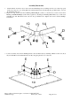
Assembly Instructions 4. Screw 3 Cam Bolts all the way into the small holes located on Side Panel Left (6) as shown below. Insert the M8 x 30 mm Dowel (C) into the end holes as a guide, attach assembly Bottom Panel (10) and Stretcher (5) to the Side Panel Left (6) by engaging Cam Locks (A). 5. Repeat last step with Large Side Panel (7). A C C 7 B B 5 10 6 6. Screw 5 Cam Bolts all the way into the small holes located on Front Panel (8) as shown below.
Assembly Instructions 8. Secure assembly Lower Front Molding Frame to the Side Panel Left (6) and Side Panel Right (8) by attaching 2 Plastic Connectors (D) at the joints with the M3.5x12 mm Pan Head Screws (E) into the pilot holes. D E 12 14 E 8 10 6 7 9. Attach 2 Plastic Connectors (D) to the Upper Front Molding Left (2) making sure they are centered properly and bottom edges are even. Using M3.5x12 mm Pan Head Screws (E) through the pre-drilled holes of Upper Front Molding Left (2). 10.
Assembly Instructions 11. Insert four M8 x 30 mm Dowel (C) into the end holes at the bottom of Top Panel (1) as a guide, Connect assembly Upper Front Molding Frame to Top Panel (1) by attaching 6 Plastic Connectors (D) at the joint with M3.5x12 mm Pan Head Screws (E), using the pilot holes as a reference. E E E D D C C 1 12. Screw 10 Cam Bolts (B) all the way into the small holes located on Top Panel (1).
Assembly Instructions 13. Set the Shelf Pins (J) at your desired height at the same level. Tilt and install Adjustable Shelves (9) in place. 1 J 7 J 8 J 6 9 10 9 14. Plug Plastic Covers (K) to cover the visible Cam Locks inside the cabinet. 15. Expand the Back Panel (11) and attach to the back edges of assembled frame making sure the margins along all edges are equal. Attach the Back Panel (11) in place by using M2x19 mm Pan Head Screws (H) through the pre-drilled holes of Back Panel.
Assembly Instructions NOTE: If you buy more than one unit, the stacking configuration can be available. 16. This cabinet featured stacking configuration. Repeat the same procedure to assemble the other corner unit. Place one unit on the top of the other base unit making sure it is centered properly and back edges are even. Using the Metal Bracket (F) as a template, mark the mounting hole locations at the back side of the Base Top Panel and Hutch Side Panels, as shown in the illustration.
Care and Maintenance Use a soft, clean cloth that will not scratch the surface when dusting. Use of furniture polishes is not necessary. Should you choose to use polishes, test in an inconspicuous area first. Using solvents of any kind on your furniture may damage the finish. Never use water to clean your furniture as it may cause damage to the finish. Always use coasters under beverage glasses and flowerpots. Liquid spills should be removed immediately.