P1 Item #1003 202 193 Model #94468 UL Model #68-ATR USE AND CARE GUIDE ALTURA II 68-INCH CEILING FAN Questions, problems, missing parts? Before returning to the store, call Home Decorators Collection Customer Service 8 a.m. - 7 p.m., EST, Monday-Friday, 9 a.m. - 6 p.m., EST, Saturday 1-800-986-3460 HOMEDEPOT.COM/HOMEDECORATORS THANK YOU We appreciate the trust and confidence you have placed in Home Decorators Collection through the purchase of this ceiling fan.
Table of Contents Table of Contents................................................................. 2 Assembly............................................................................... 7 Safety Information................................................................ 2 Operation............................................................................ 14 Warranty................................................................................ 3 Care and Cleaning................................
Warranty The supplier warrants the fan motor to be free from defects in workmanship and material present at time of shipment from the factory for a lifetime after the date of purchase by the original purchaser. The supplier also warrants that all other fan parts, excluding any glass or acrylic blades, to be free from defects in workmanship and material at the time of shipment from the factory for a period of two years after the date of purchase by the original purchaser.
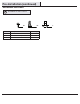
Pre-Installation (continued) HARDWARE INCLUDED NOTE: Hardware not shown to actual size.
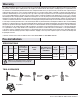
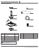
Pre-Installation (continued) PACKAGE CONTENTS A F B G B C H D I E Part Description Quantity A Slide-on mounting bracket (inside canopy) 1 B Ball/downrod assembly C Part Description Quantity F Decorative motor collar cover 1 G Blade 5 1 H Switch cup adaptor 1 Canopy with canopy ring attached 1 I Remote control (battery included) 1 D Fan-motor assembly 1 E Switch cup (receiver included) 1 IMPORTANT: This product and/or components are governed by one or more of the foll
Installation MOUNTING OPTIONS WARNING: To reduce the risk of fire, electric shock or personal injury, mount to outlet box marked “Acceptable for fan support of 50lbs. (22.7kg) or less”, and use screws provided with the outlet box. An outlet box commonly used for the support of lighting fixtures may not be acceptable for fan support and may need to be replaced. If in doubt, consult a qualified electrician.
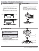
Assembly - Standard Ceiling Mount 1 2 Preparing for mounting □ Remove the canopy ring (L) from the canopy (C) by turning □ □ the ring counter-clockwise until it unlocks. Remove the mounting bracket (A) from the canopy (C) by loosening the two screws (HH) located in the “L shaped” slots Remove and save the two non-slotted screws (SS) in the round holes. This will enable you to remove the mounting bracket (A).
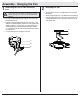
Assembly - Hanging the Fan 1 2 Attaching the fan to the electrical box □ Carefully lift the fan motor assembly (D) up to the mounting WARNING: To reduce the risk fo fire, electric shock or personal injury, mount to outlet box marked “acceptable for fan support of 50 lbs. (22.7kg) or less”, and use screws provided with the outlet box. bracket (A). □ Seat the hanger ball portion of the ball/downrod assembly (B) in the mounting bracket (A) socket.
Assembly - Hanging the Fan (continued) 3 Making the electrical connection WARNING: Each wire nut supplied with this fan is designed to accept up to one 12-gauge house wire and two wires from the fan. If you have larger than 12-gauge house wiring or more than one house wire to connect to the fan wiring, consult an electrician for the proper size wire nuts to use. Outlet box in the ceiling (OO) Black Black IMPORTANT: Use the plastic wire connectors (BB) supplied with your fan.
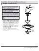
Assembly - Hanging the Fan (continued) 4 5 Wrapping the extra wire Mounting the fan-motor assembly (standard mount) WARNING: When using the standard ball/downrod mounting, the tab in the ring at the bottom of the mounting bracket must rest in the groove of the hanger ball. Failure to properly seat the tab in the groove could cause damage to the wiring. NOTE: Follow this step ONLY if you did not cut the extra length off from the wires coming from the ceiling fan.
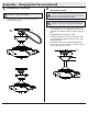
Assembly - Hanging the Fan (continued) 6 Attaching the fan blades AA □ Attach blade (G) to blade bracket (J) using the decorative □ □ nuts (CC) and blade attachment screws (AA) provided. Insert a blade attachment screw (AA) through a hole in the blade (G) and the blade bracket (J) and into the decorative nut (CC). Repeat for the two remaining holes in the blade (G). Tighten each screw (AA) securely. Repeat these steps for the remaining blades.
Optional Installation - Installing the Light Kit to the Altura Fan 1 2 Removing the receiver from the switch cup □ Remove the two screws (KK save for later use) that hold the □ □ Wiring the light kit to the fan CAUTION: Over lamping the fan will result in the fan lights shutting down until the proper wattage bulbs are installed. Reset the lights by turning off the power, replacing the bulbs with the correct wattage bulbs, and turning the power back on. Do not exceed 180 total watts.
Optional Installation - (continued) 3 4 Reinstalling the receiver in the switch cup □ □ □ □ □ Attaching the switch cup and light kit to the fan CAUTION: To reduce the risk of electric shock, disconnect the electrical supply circuit to the fan before installing the switch cup. Insert the black and white wires (LL) from the light kit (A) through the center hole of the receiver (NN) one at a time.
Operating Your Fan and Remote Control Operating the fan NOTE: Do not wait for the fan to stop before pressing the reverse button. The fan will not reverse direction if the fan is not moving. Remote Control - Your fan is equipped with a remote control to operate the speed and lights of your new ceiling fan. Speed setting for warm or cool weather depends on factors such as the room size, ceiling height, number of fans and so on. Warm weather - (Forward) A downward airflow creates a cooling effect.
Operating Your Fan and Remote Control Learning process Remote control operation 3 = High speed NOTE: After the AC power is on, do not press any other button on the remote control before pressing the “Power” button (VV). Doing so will cause the procedure to fail. 2 = Medium speed 1 = Low speed NOTE: The remote control can learn multiple receivers. Make sure no other receivers are operating during the learning process. Separate the fan power switches by approximately 2 meters. (VV) = Power off.
Care and Cleaning WARNING: Make sure the power is off before cleaning your fan. □ Because of the fan’s natural movement, some connections may become loose. Check the support connections, brackets, and blade attachments twice a year. Make sure they are secure. It is not necessary to remove the fan from the ceiling. □ Clean your fan periodically to help maintain its new appearance over the years.
This equipment has been tested and found to comply with the limits for a Class B digital device, pursuant to Part 15 of the FCC Rules. These limits are designed to provide reasonable protection against harmful interference in a residential installation. This equipment generates uses and can radiate radio frequency energy and, if not installed and used in accordance with the instructions, may cause harmful interference to radio communications.
Artículo #1003 202 193 Modelo #94468 Modelo #68-ATR-UL P1 GUÍA DE USO Y MANTENIMIENTO VENTILADOR DE TECHO ALTURA II, 68 PLG ¿Preguntas, problemas o piezas en falta? Antes de regresar a la tienda, llama al servicio al cliente de Home Decorators Collection, De lunes a viernes, entre 8:00 a.m. y 7:00 p.m. (Este), y los sábados de 9:00 a.m. a 6:00 p.m. (Este). 1-800-986-3460 HOMEDEPOT.
Tabla de contenido Tabla de contenido............................................................... 2 Ensamblaje............................................................................ 7 Información de seguridad................................................... 2 Funcionamiento.................................................................. 14 Garantía................................................................................. 3 Mantenimiento y limpieza.....................................
Garantía El proveedor garantiza de por vida, a partir de la fecha de adquisición por el comprador original, que el motor del ventilador no presenta defectos de fabricación ni de materiales al momento del envío desde la fábrica.
Preinstalación (continuación) SE INCLUYEN HERRAJES NOTA: Los herrajes no se muestran en tamaño real.
Preinstalación (continuación) CONTENIDO DEL PAQUETE A F B G B C H D I E Pieza Descripción Cantidad A Soporte de montaje deslizante (dentro de la cubierta) 1 B Conjunto del tubo bajante/bola C Pieza Descripción Cantidad F Cubierta decorativa del collarín del motor 1 G Aspa 5 1 H Adaptador de la caja del interruptor 1 Cubierta con aro incorporado 1 I Control remoto (incluye batería) 1 D Conjunto motor-ventilador 1 E Caja del interruptor (receptor incluido) 1 IMPORTANTE
Instalación OPCIONES DE MONTAJE ADVERTENCIA: Para reducir el riesgo de incendio, descarga eléctrica u otras lesiones, instala sólo en una caja eléctrica clasificada como “apropiada para sostener ventiladores de 50 lb (22.7 kg) o menos”, y usa sólo los tornillos incluidos con la caja eléctrica. Las cajas eléctricas que suelen utilizarse para el soporte de lámparas pudieran no servir como soporte del ventilador y tal vez deban reemplazarse. En caso de duda, consulta a un electricista calificado.
Ensamblaje - Montaje estándar en techo 1 2 Preparación para el montaje □ Retira el aro de cubierta (L) de la cubierta (C), girándolo en □ □ Cómo tender los cables □ sentido contrario a las manecillas del reloj hasta soltarlo. Retira el soporte de montaje (A) de la cubierta (C) aflojando los dos tornillos (HH) ubicados en las “ranuras en L”. Quita y guarda los dos tornillos de la cubierta (SS) en los orificios redondos. Esto te permitirá retirar el soporte de montaje (A).
Ensamblaje - Cómo colgar el ventilador 1 2 Cómo fijar el ventilador a la caja eléctrica Cómo colgar el ventilador □ Levanta con cuidado el conjunto motor-ventilador (D) hasta el ADVERTENCIA: Para reducir el riesgo de incendio, descarga eléctrica o lesiones personales, instala solo en una caja eléctrica clasificada como “apropiada para sostener ventiladores de 50 lb (22.7kg) o menos” y usa los tornillos que vienen con ella. soporte de montaje (A).
Ensamblaje - Cómo colgar el ventilador (continuación) 3 Cómo hacer las conexiones eléctricas ADVERTENCIA: Cada tuerca para cable incluida con este ventilador está diseñada para cables domésticos calibre 12 como máximo y dos cables del ventilador. Si tu cableado doméstico tiene calibre mayor de 12 o más de un cable para conectar al cableado del ventilador, consulta a un electricista para saber el tamaño adecuado de las tuercas a usar para los cables.
Ensamblaje - Cómo colgar el ventilador (continuación) 4 5 Cómo enrollar el cable sobrante ADVERTENCIA: Cuando uses el montaje estándar del tubo bajante/bola, la pestaña en el aro de la parte inferior del soporte de montaje tiene que encajar en la ranura de la bola de soporte. Si la pestaña no se asienta bien en la ranura, se puede dañar el cableado. NOTA: Sigue estos pasos SOLO si no cortaste el cable sobrante del ventilador de techo.
Ensamblaje - Cómo colgar el ventilador (continuación) 6 Cómo fijar las aspas del ventilador AA □ Fija el aspa (G) a su soporte (J) con las tuercas decorativas (CC) □ □ J y los tornillos de fijación correspondiente (AA) que se incluyen. Inserta un tornillo de montaje de aspa (AA) a través del orificio de ella (G), su soporte (J) y la tuerca decorativa (CC). Repite para los otros dos orificios restantes del aspa (G). Aprieta firmemente todos los tornillos (AA).
Instalación opcional - Cómo instalar el kit de luces al ventilador Altura 1 2 Cómo quitar el receptor de la caja del interruptor □ Quita los dos tornillos (KK, guardarlos para usar más adelante) □ □ Cómo instalar el cableado del kit de luces al ventilador PRECAUCIÓN: Si se enciende el ventilador en exceso, las luces del ventilador se apagarán hasta que se instalen las bombillas de potencia adecuada.
Instalación opcional - (Continuación) 3 4 Cómo reinstalar el receptor en la caja del interruptor □ □ □ □ □ Cómo instalar el kit de luces y la caja del interruptor al ventilador PRECAUCIÓN: Para reducir el riesgo de descargas eléctricas, desconecta el circuito de energía del ventilador antes de instalar la caja del interruptor. Pasa los cables negro y blanco (LL) del kit de luces (A) a través del orificio central del receptor (NN), uno a la vez.
Cómo usar tu ventilador y control remoto Cómo usar el ventilador NOTA: No esperes a que el ventilador se detenga antes de presionar el botón de reversa. Si el ventilador no está en movimiento, no cambiará de dirección. Control Remoto: Tu ventilador está equipado con un control remoto para operar la velocidad y las luces de tu nuevo ventilador de techo.
Cómo usar tu ventilador y control remoto Proceso de memorización Operación por control remoto 3 = Alta velocidad NOTA: Después de que la corriente alterna esté encendida, no presiones ningún otro botón del control remoto antes de presionar el botón “Power” (VV). Si lo haces, el procedimiento puede fallar. 2 = Moderada velocidad NOTA: El control remoto puede memorizar múltiples receptores. Asegura que ningún otro receptor esté funcionando durante el proceso de memorización.
Mantenimiento y limpieza ADVERTENCIA: Asegura que la fuente de corriente está apagada antes de limpiar el ventilador. □ Debido al movimiento natural del ventilador, algunas conexiones pueden aflojarse. Revisar dos veces al año las conexiones de soporte, los soportes y los accesorios de las aspas. Comprobar que estén seguros. No es necesario desmontar el ventilador del cielo raso. □ Hay que limpiar el ventilador con frecuencia para que luzca como nuevo al paso de los años. No usar agua al limpiarlo.
Este equipo ha sido comprobado y se determinó que cumple con los límites establecidos para un dispositivo digital Clase B, de acuerdo con la Parte 15 de las Normas FCC. Estos límites fueron establecidos para dar protección razonable contra la interferencia dañina en uso residencial. Este equipo genera, usa y puede irradiar energía en frecuencias de radio y, de no ser instalado y utilizado de acuerdo con las instrucciones, puede causar una interferencia dañina a comunicaciones radiales.