Item # 1006 527 196 Model #FZA71015R-STS USE AND CARE GUIDE ST. CHARLES 5PC ALUM FIRE CHAT SET - CHAIR Questions, problems, missing parts? Before returning to the store, call Home Decorators Collection Customer Service. 8 a.m. - 7 p.m., EST, Monday - Friday, 9 a.m. - 6 p.m., EST, Saturday 1-800-986-3460 HOMEDEPOT.COM/HOMEDECORATORS THANK YOU We appreciate the trust and confidence you have placed in Home Decorators Collection through the purchase of this chair.
Table of Contents Table of Contents.......................................................... 2 Pre-Assembly ................................................................ 3 Planning Assembly .................................................................. 3 Hardware Included .................................................................4 Package Contents ....................................................................4 Important Safety Instructions ...................................
Warranty 5 YEAR FRAME AND 5 YEAR FABRIC LIMITED WARRANTY WHAT IS COVERED We warrant the frame to be free of manufacturing defects to the original purchaser f years, and a five year limited warranty for the fabric. WHAT IS NOT COVERED It remains the customer’s responsibility for freight and packaging charges to and from our service center. This warranty does not cover is warranty. We reserve the right to make substitutions with similar merchandise, if the model in question is no longer in production.
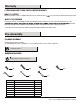
Pre-Assembly PACKAGE CONTENTS A B C D E F J I K H G Part Description Quantity A Support Bar 4 B Backrest 4 C Left Arm 4 D Right Arm 4 E Seat 4 F Support Tube 4 G Left Leg 4 H Right Leg 4 I Connector Bar 4 J Back Cushion 4 K Seat Cushion 4 4
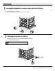
l Assembly 1 Inserting the Support Bar, Backrest and Seat to the Left Arm Place the left arm (C) on a soft surface. Insert the support bar (A), backrest (B) and seat (E) to the left arm (C). A B E C 2 Attaching the Seat to the Left Arm Attach the seat (E) to the left arm (C) using M6x35 combination bolts (BB). Do not tighten all bolts at this step. NOTE: Loosely tighten the bolts using the hex wrench (EE). E BB C 5 HOMEDEPOT.
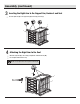
l (continued) Assembly 3 Inserting the Right Arm to the Support Bar, Backrest and Seat Insert the right arm (D) to the support bar (A), backrest (B) and seat (E). D B A E 4 Attaching the Right Arm to the Seat Attach the right arm (D) to the seat (E) using M6x35 combination bolts (BB). Do not tighten all bolts at this step. NOTE: Loosely tighten the bolts using the hex wrench (EE).
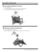
l (continued) Assembly 5 Connecting the Support Bar to the Arms Turn the chair right side up. Connect the support bar (A) to the left arm (C) and right arm (D) using M6x20 bolts (DD). Once all bolts are in place, fully tighten all bolts using the hex wrench (EE). DD A D C 6 Attaching the Support Tube to the Seat Place the chair upside down on a soft surface. Attach the support tube (F) to the seat (E) using M8x28 combination bolts (CC) and the wrench (FF). CC CC E F 7 HOMEDEPOT.
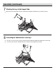
l (continued) Assembly 7 Attaching the Legs to the Support Tube Attach the left leg (G) and the right leg (H) to the support tube (F) using M8x28 combination bolts (CC) and the wrench (FF). CC CC H G F 8 Connecting the Connector Bar to the Legs Connect the connector bar (I) to the left leg (G) and the right leg (H) using M6x20 combination bolts (AA) and the hex wrench (EE). Once all of the bolts are in place, fully tighten all the bolts using the hex wrench (EE) and the wrench (FF).
l (continued) Assembly 9 Checking the Chair Turn the chair right side up. Ensure all connections are secure before use. J K Care and Cleaning For best results, clean the chair with a damp cloth and dry thoroughly. This will help prevent mildew by removing dirt particles that may accumulate. Do not clean with abrasive materials, bleach, or solvents. Store the chair in a dry, sheltered place when not in use.
Questions, problems, missing parts? Before returning to the store, call Home Decorators Collection Customer Service. 8 a.m. - 7 p.m., EST, Monday - Friday, 9 a.m. - 6 p.m., EST, Saturday 1-800-986-3460 HOMEDEPOT.COM/HOMEDECORATORS Retain this manual for future use.
Item # 1006 325 655 Model # FHTM80223 USE AND CARE GUIDE ST. CHARLES LP FIREPIT Factory fire table ID # FHTM80223 Questions, problems, missing parts? Before returning to the store, call Home Decorators Collection Customer Service. 8 a.m. - 7 p.m., EST, Monday - Friday, 9 a.m. - 6 p.m., EST, Saturday 1-800-986-3460 HOMEDEPOT.
Table of Contents WARNING FOR YOUR SAFETY: For Outdoor Use Only (outside, non-enclosed area). Do Not Use For Cooking. Installation and service must be performed by a qualified installer, service agency, or the gas supplier. Table of Contents Table of Contents. . . . . . . . . . . . . . . . . . . . . . . . . . . . . . 2 Important Safety Information. . . . . . . . . . . . . . . . . . . . .2 Propane (LP) Dangers and Warnings. . . . . . . . . . . . . .5 Hose & Regulator Assembly and Replacement. . . . . .
Important Safety Information WARNING: Fire table is for outdoor use only. Installation and repair should be done by a qualified service person. The appliance should be inspected before use and at least annually by a qualified service person. More frequent cleaning may be required as necessary. It is imperative that the control compartment, burners and circulating air passageways of the appliance are kept clean.
Important Safety Information (continued) The use of alcohol, prescription or non-prescription drugs may impair an individual’s ability to properly assemble or safely operate this outdoor fire table. DO NOT use in an explosive atmosphere. Keep gas fire table area clear and free from combustible materials, such as gasoline. This outdoor fire table is not to be installed or used in or on recreational vehicles and/or boats. Always use in accordance with all applicable local, provincial and national codes.
Important Safety Information (continued) ATTENTION: Any alteration of the outdoor fire table that is not specifically directed in the operations manual will void manufacturer warranty. PROPANE (LP) DANGERS AND WARNINGS LP GAS LP gas is flammable and hazardous if handled improperly. Familiarize yourself with its hazards before using any LP gas product. PROPANE HAZARDS Flammable, explosive under pressure, heavier than air and settles in pools in low areas. In its natural state, propane has no odor.
Important Safety Information (continued) HOSE AND REGULATOR ASSEMBLY AND REPLACEMENT 1. This fire table comes equipped with a standard LP gas hose and regulator including the appliance side connection for a CGA No. 791 Cylinder Connection Device. The LP gas hose and regulator supplied with this fire table must be used. Only a hose and regulator specified by manufacturer can be used for replacement. a. The CGA No.
Warranty 1 YEAR FRAME LIMITED WARRANTY WHAT IS COVERED We warrant the frames to be free of manufacturing defects to the original purchaser for one year. WHAT IS NOT COVERED It remains the customer’s responsibility for freight and packaging charges to and from our service center. This warranty does not cover s warranty. We reserve the right to make substitutions with similar merchandise, if the model in question is no longer in production.
Pre-assembly (continued) HARDWARE INCLUDED NOTE: Hardware not shown to actual size.
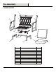
Pre-assembly (continued) PACKAGE CONTENTS S M B E N O P Q G R L K G F I G C D H A J Part Description Quantity A Knob 1 B C Table Top Right Front Leg 1 1 D Left Front Leg 1 E F Left Rear Leg Right Rear Leg 1 1 G Side Panel 3 H I Door Limit Tube 1 1 J Tank Support 1 K L Glass Beads AAA Battery 1 1 M Square Burner Bowl 1 N O Burner Ring Pilot Housing 1 1 P Manual Electric Igniter 1 Q R Control Knob Regulator/Hose 1 1 S Burner Lid 1 9 WARNING: Failure
Assembly 1 Connecting the Legs to the Table Top NOTE: Pay attention to the direction of control knob and the legs. They must be placed as the step shows. Place the table top (B) upside down on a soft surface. Attach the right front leg (C), left front leg (D), left rear leg (E) and right rear leg (F) to the table top (B) using M6X15 combination bolts (AA), as shown below. AA AA Do not tighten the bolts at this step. NOTE: Loosely tighten all the bolts using hex wrench (EE).
Assembly (continued) 3 Connecting the Limit Tube to the Right Front Leg and the Left Rear Leg Attach the limit tube (I) to the right front leg (C) and left rear leg (E) using M6X15 combination bolts (AA). Do not tighten the bolts at this step. AA NOTE: Loosely tighten all the bolts using hex wrench (EE). E C I 4 Connecting the Tank Support Attach the tank support (J) to the right front leg (C), left front leg (D), left rear leg (E) and right rear leg (F) using M6X15 combination bolts (AA).
Assembly (continued) 5 Connecting the Door Attach the door (H) to the left front leg (D) using a plastic washer 1 (CC). Attach the door (H) to the tank support (J) using a M6X12 countersunk bolt (BB) and a plastic washer 2 (DD). Do not tighten the bolts at this step. J NOTE: Loosely tighten all the bolts using hex wrench (EE). BB DD D H 6 Attaching the Knob and Checking the Table Once all of the bolts are in place, fully tighten all the bolts using the hex wrench (EE).
Assembly (continued) 7 Placing the Glass Beads CAUTION: To ensure proper function, the screen on the pilot housing should be free of glass beads. Place the glass beads (K) into the square burner bowl (M). K M Pilot Housing CORRECT Burner Tube do not block opening INCORRECT Pilot 8 Placing the Burner Lid WARNING: S Place the burner lid (S) over the square burner bowl (B). Make sure to remove the burner lid (S) before lighting. Do not place the lid back onto burner bowl until it has cooled down.
Operation 1 Installing the LP Gas Tank CAUTION: The Make sure LP gas tank valve is closed. Loosen LP gas tank retainer bolt by turning counterclockwise. on. Secure tank by turning LP gas tank retainer bolt clockwise until tight. 2 Connecting the LP Gas Tank Before connecting, be sure there is no debris caught in the head of the LP gas tank, in the head of the regulator valve or in the head of the burner ports. Connect the regulator/hose assembly to tank by turning knob clockwise until it stops.
Operation (continued) 3 Disconnecting the LP Gas Tank NOTE: Before disconnecting make sure the LP gas tank valve is “CLOSED”. Disconnect regulator/hose assembly from LP gas by turning knob conterclockwise until it is loose. Place the protective cap cover on the LP gas tank and store it outdoors in a well-ventilated area out of direct sunlight. 4 Checking for Leaks and Burner Connections CAUTION: an explosion which can cause death, serious bodily injury or damage to property.
Operation (continued) 5 Tank/Gas Line Connection Leak Test Make 2-3 oz. of leak detection solution by mixing one part liquid dishwashing soap with three parts water. Make sure the control knob is in the “OFF” position. Connect LP gas tank per “CONNECTING LP GAS TANK” section. Turn LP gas tank valve to “OPEN”. a) If any bubbles appear, turn LP gas tank valve to “CLOSED”, reconnect and re-test.
Operation (continued) 7 Closing the Door 17 HOMEDEPOT.
Operation (continued) CAUTION: Failure to follow these instructions could cause a fire or an explosion which can cause death, serious bodily injury or damage to property. WARNING: CAUTION: Keep outdoor gas appliance area clear and free from combustible materials, gasoline and other flammable vapors and liquids. CAUTION: 15.7 in-23.5in 40-60cm CAUTION: LIGHTING 1. Make sure all labels, packaging and protective films have been removed from the outdoor fire table. 2.
Operation (continued) LIGHTING (CONTINUED) 11. If igniter does not light burner: a. Wearing heat-resistant gloves, position a long, lit match or long, lit butane lighter near the pilot housing. b. Push and turn control knob to “ON”. c. Remove match/lighter once burner is lit. 12. After lighting, observe the burner flame and make sure all burner ports are lit and flame height matches illustration on page 18.
Care and Maintenance Cleaning Surfaces 1. Wipe surfaces clean with mild dishwashing detergent or baking soda mixed with water. 2. For stubborn stains, use a citrus-based cleaner and a nylon scrubbing brush. 3. Rinse clean with water. 4. Allow to air dry. Before Storing 1. Turn LP gas tank valve to “CLOSED”. 2. Turn control knob to the “OFF” position. NOTE: A “poof” sound is normal as the last of the LP gas is burned. 3. Disconnect LP gas tank per “Disconnecting LP Gas Tank” section. 4. Clean all surfaces.
Troubleshooting The burner will not light using the igniter. The burner will not light with a match. The LP gas tank valve is closed. Make sure that the regulator is securely attached to the LP gas tank per the "Installing the LP Gas Tank" section. Then turn the LP gas tank valve to "OPEN." The LP gas tank is low or empty. Exchange, refill or replace the LP gas tank. The LP gas leaks. 1. Turn the LP gas tank valve to “CLOSED”. 2. Wait 5 minutes for the gas to clear. 3.
Troubleshooting (Continued) The tank is out of gas. Exchange, refill or replace the LP gas tank. 1. Turn control knob to “OFF”. There is a sudden drop in gas flow, or the flame height is reduced. The overfilling prevention device may have been activated. There is an irregular flame pattern, or the flame does not run There is no gas flow. the full length of the burner. The flame is yellow or orange. 2. Wait 30 seconds and light the outdoor fire table per the “Lighting” section. 3.
Questions, problems, missing parts? Before returning to the store, call Home Decorators Collection Customer Service. 8 a.m. - 7 p.m., EST, Monday - Friday, 9 a.m. - 6 p.m., EST, Saturday 1-800-986-3460 HOMEDEPOT.COM/HOMEDECORATORS Retain this manual for future use.