
Installation Guide

2
Introduction
WARNING! If installed improperly, re, explosion or asphyxiation may result. Installation
instructions and applicable local codes must be strictly followed.
CALIFORNIA PROPOSITION 65 WARNING: This product contains one or more chemicals
known to the State of California to cause cancer, birth defects, or other reproductive harm.
Wash hands after handling.
1.2 Limitations of Manual
This System Design and Installation Manual is intended to assist the qualied gas pipe install-
er in the design, installation, and testing of the HOME-FLEX® exible gas piping system for
residential, commercial, and industrial buildings. It is not possible for this guide to anticipate
every variation in construction style, building conguration, appliance requirement, or local
restriction. This document will not cover every application. The user should either exercise his
own engineering judgment on system design and installation, or seek technical input from
qualied sources. Additional information on gas piping systems is available from your local
gas utility or propane supplier. General usage guidelines of HOME-FLEX® exible gas piping
are outlined as follows:
The piping system is for use with fuel gases only and is intended for operating pressures
not exceeding 5 PSI (34.5 kPa). The maximum actual operating pressure, including transients,
shall not in any case exceed 6.5 PSI (44.8 kPa) for 5 PSI (34.5 kPa) rating.
Precautions shall be taken by the installer to ensure any exposed tubing is not damaged or
abused during building construction or reconstruction.
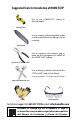
Only the components provided or specied by Valencia Pipe Company, Inc. are to be used in
the installation.
The size and depth of installation clearance holes or notches for routing the tubing through
wall studs and joists shall comply with the requirements of the local building code.
Concealed tubing shall be protected from puncture threats, using the shielding devices spec-
ied by Valencia Pipe Company, at all points of penetration through studs, joists, plates or
similar structures. The extent of protection shall be dened as follows:
• At points of penetration less than 2" (50.8 mm) from any edge of a stud, joist, plate,
etc., a listed striker plate is required to provide protection at the area of support
and within 5 in (127 mm) of each side (if appropriate) of the support.
• At points of penetration 2" - 3" (50.8 to 76.2 mm) from any edge of a stud, joist,
plate, etc., a listed striker plate is required to provide protection throughout the
area of support.
• At points of penetration greater than 3" (76.2 mm) from any edge of a stud, joist,
plate, etc., no protection is required.
• Tubing routed horizontally through studs shall be protected from puncture
threats between the studs using the shielding devices specied.
• Tubing greater than 1" (25.4 mm) inside diameter installed within hollow cavity
walls of 2 x 4 construction shall be protected along the entire concealed length in
the manner and using the shielding devices specied by Valencia Pipe Company.
• The width of the installed striker plate, at the points of penetration through wall
studs, oor joists, plates, sills, etc., shall be at least 1.5 times the outside diameter
of the tubing.
The inspection, testing and purging of the installation shall be performed using the proce-
dures specied in Part 4, General, of the National Fuel Gas Code (ANSI Z223.1/NFPA 54), and/
or the Natural Gas and Propane Installation Code (CSA B149.1), the International Fuel Gas Code,
the Uniform Plumbing Code, or in accordance with the requirements of the applicable local