
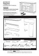
Owner's manual
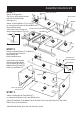
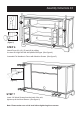

STEP 4
Assembly Instructions 3/4
Cam Lock Screws
Attach Base (I) to the unit with Cam Locks.
Put 3X Cam Lock Screws into the pre-drelled holes of Base (I) as shown, then attach
Back Support (R) to Base (I) with Cam Locks and attach Side Panel (B) and (C), Plinth (H)
to the unit with Cam Locks.
Tighten up Leg (S) in the pre-drilled hole of unit as shown.
I
B
R
S
H
C
Cam Lock
A
Adjustable Pin
Cam Lock
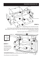
STEP 5
Slide Back Panels
(J) and (K) into place.
Place Top (A) onto
the unit, using
Cam Locks.
Insert Adjustable Pins into
side panels and middle panels at the desired level. (See figure 3)
Place Shelves (L) and (M) into position.
L
J
K
M
M
M
M
K
(Figure 3)