
Instructions / Assembly


Assembly Instructions 4/6
B
G
A
H
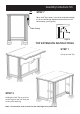
STEP 6
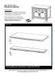
Attach Top (A) to unit with
Cam Locks.
Insert Adjustable Pins into side
panels and middle panel at
desired level, then place
shelves (H) into position.
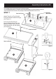
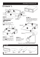
Slide Drawers (L) into position.
Figure 8
Figure 7
L
H
L
Adjustable Pin
Cam Lock
Wood Screw
(short)
Wood Screw
(short)
Magnet
C
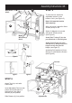
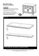
STEP 5
To level the unit, adjust the
adjustable levelers on the
bottom of unit. (see Figure 5)
Note: Unit must be level to
work properly.
After unit is level, attach 8x Wood
Screws (short) to unit.
Attach 2x Magnet to front rails
with Wood Screws (short).
(see Figure 6)
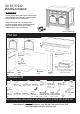
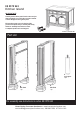
Attach Back Turning (G) into the
pre-drilled hole of unit and tighten.
Attach Doors (B) and (C) to the
side panels, by sliding the door lift
hinges into the side panel lift
hinges. (see Figure 7)
Assemble Pull Handles to Doors
(B) and (C) with Machine Screws.
(see Figure 8)
Figure 6
Figure 5