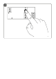
Installations- und Bedienungsanleitung Installation instruction and operating manual Schaltplatine Switch Circuit Board HmIP-PCBS S. 2 p.
Lieferumfang Anzahl Bezeichnung 1 Homematic IP Schaltplatine 1 Bedienungsanleitung Dokumentation © 2017 eQ-3 AG, Deutschland Alle Rechte vorbehalten. Ohne schriftliche Zustimmung des Herausgebers darf diese Anleitung auch nicht auszugsweise in irgendeiner Form reproduziert werden oder unter Verwendung elektronischer, mechanischer oder chemischer Verfahren vervielfältigt oder verarbeitet werden. Es ist möglich, dass die vorliegende Anleitung noch drucktechnische Mängel oder Druckfehler aufweist.
1 A B C D E F
2 3
4
Inhaltsverzeichnis 1 2 3 4 5 Hinweise zur Anleitung.................................................... 7 Gefahrenhinweise............................................................. 7 Funktion und Geräteübersicht.....................................10 Allgemeine Systeminformationen............................... 11 Inbetriebnahme............................................................... 11 5.1 5.2 5.3 5.4 6 7 Einbau...............................................................................
Hinweise zur Anleitung 1 Hinweise zur Anleitung Lesen Sie diese Anleitung sorgfältig, bevor Sie Ihre Homematic IP Geräte in Betrieb nehmen. Bewahren Sie die Anleitung zum späteren Nachschlagen auf! Wenn Sie das Gerät anderen Personen zur Nutzung überlassen, übergeben Sie auch diese Anleitung. Benutzte Symbole: Achtung! Hier wird auf eine Gefahr hingewiesen. Hinweis.
Gefahrenhinweise Aus Sicherheits- und Zulassungsgründen (CE) ist das eigenmächtige Umbauen und/oder Verändern des Gerätes nicht gestattet. Betreiben Sie das Gerät nur in trockener sowie staubfreier Umgebung, setzen Sie es keinem Einfluss von Feuchtigkeit, Vibrationen, ständiger Sonnen- oder anderer Wärmeeinstrahlung, Kälte und keinen mechanischen Belastungen aus. Das Gerät ist kein Spielzeug! Erlauben Sie Kindern nicht damit zu spielen. Lassen Sie das Verpackungsmaterial nicht achtlos liegen.
Gefahrenhinweise Alle Lastangaben beziehen sich auf ohmsche Lasten! Belasten Sie das Gerät nur bis zur angegebenen Leistungsgrenze. Eine Überlastung kann zur Zerstörung des Gerätes, zu einem Brand oder elektrischen Unfall führen. Eine entsprechende Sicherung ist an den Schaltausgängen (Relais, Transistor) vorzusehen! Zur Gewährleistung der elektrischen Sicherheit muss es sich bei der speisenden Quelle um eine Sicherheits-Schutzkleinspannung handeln.
Funktion und Geräteübersicht 3 Funktion und Geräteübersicht Die Homematic IP Schaltplatine ermöglicht das Schalten von bspw. eines Schalter- oder Tastereingangs, 12 V-Signalgebers oder von LEDs per Funk im Kleinspannungsbereich. Die Platine ist für den Betrieb an einer permanenten Stromversorgung vorgesehen. Der Schaltausgang der Platine bietet folgende Verwendungsmöglichkeiten: Das Gerät verfügt über ein Miniatur-Relais mit einer Schaltleistung bis 30 V/1 A.
Allgemeine Systeminformationen 4 Allgemeine Systeminformationen Dieses Gerät ist Teil des Homematic IP Smart-Home-Systems und kommuniziert über das Homematic IP Funkprotokoll. Alle Geräte des Systems können komfortabel und individuell per Smartphone über die Homematic IP App konfiguriert werden. Alternativ haben Sie die Möglichkeit, Homematic IP Geräte über die Homematic Zentrale CCU2 oder in Verbindung mit vielen Partnerlösungen zu betreiben.
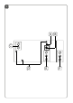
Inbetriebnahme Starre Leitung [mm2] Flexible Leitung mit und ohne Aderendhülse [mm2] 0,75 – 1,0 0,75 – 1,0 5.2 Anschlussbelegung 5.2.1 Konfiguration mit Open-Collector-Ausgang: s. Abbildung 2 5.2.2 Konfiguration mit Relais-Schaltausgang: s. Abbildung 3 5.3 Anschlussbeispiele Die Platine kann in einem Betriebsspannungsbereich von 5 bis 25 V betrieben werden.
Inbetriebnahme (1) Ansteuerung eines Schalteingangs (hier einer Mikroprozessorschaltung) und Spannungsversorgung aus dieser Schaltung: (2) Ansteuerung eines Schalteingangs (hier einer Mikroprozessorschaltung) und Spannungsversorgung aus eigener Spannungsquelle: (3) Ansteuerung eines externen Relais (mit Freilaufdiode) oder einer Lampenlast bis 0,5 A mit Last-Stromversorgung aus der Eingangsspannung: 13
Inbetriebnahme (4) Ansteuerung eines externen 5 V-Relais (mit Freilaufdiode) oder eines Optokopplers bzw.
Inbetriebnahme (5) Ansteuerung des Relaismoduls RSM1 mit Versorgung des Relaismoduls aus der Aktor-Betriebsspannung: (6) Ansteuerung des Relaismoduls RSM1 mit eigenständiger Versorgung des Relaismoduls: (7) Ansteuerung einer Last (max.
Inbetriebnahme 5.4 Anlernen Bitte lesen Sie diesen Abschnitt erst vollständig, bevor Sie mit dem Anlernen beginnen. Richten Sie zunächst Ihren Homematic IP Access Point über die Homematic IP App ein, um weitere Homematic IP Geräte im System nutzen zu können. Ausführliche Informationen dazu finden Sie in der Bedienungsanleitung des Access Points. Sie können das Gerät sowohl an den Access Point als auch an die Homematic Zentrale CCU2 anlernen.
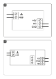
Inbetriebnahme Sie können den Anlernmodus manuell für weitere 3 Minuten starten, indem Sie die Systemtaste (B) kurz drücken (s. Abbildung 4). • • • • • • • Das Gerät erscheint automatisch in der Homematic IP App. Zur Bestätigung geben Sie in der App die letzten vier Ziffern der Gerätenummer (SGTIN) ein oder scannen Sie den QR-Code. Die Gerätenummer finden Sie auf dem Aufkleber im Lieferumfang oder direkt am Gerät. Warten Sie, bis der Anlernvorgang abgeschlossen ist.
Bedienung 6 Bedienung Nach dem Anlernen können Sie die Schaltplatine z. B. mit einer angelernten Homematic IP Fernbedienung oder über die Homematic IP App steuern und so angeschlossene Verbraucher ein- oder ausschalten. Einfache Bedienfunktionen stehen auch direkt am Gerät zur Verfügung: • Um einen Funktionstest durchzuführen oder den Aktor ein- bzw. auszuschalten, drücken Sie kurz auf die Systemtaste (B). Die Geräte-LED (A) signalisiert dabei den Schaltzustand.
Fehlerbehebung 7.2 Duty Cycle Der Duty Cycle beschreibt eine gesetzlich geregelte Begrenzung der Sendezeit von Geräten im 868 MHz-Bereich. Das Ziel dieser Regelung ist es, die Funktion aller im 868-MHz-Bereich arbeitenden Geräte zu gewährleisten. In dem von uns genutzten Frequenzbereich 868 MHz beträgt die maximale Sendezeit eines jeden Gerätes 1 % einer Stunde (also 36 Sekunden in einer Stunde). Die Geräte dürfen bei Erreichen des 1 %-Limits nicht mehr senden, bis diese zeitliche Begrenzung vorüber ist.
Fehlerbehebung 7.3 Fehlercodes und Blinkfolgen Blinkcode Bedeutung Lösung Kurzes oranges Blinken Funkübertragung/Sendeversuch/ Datenübertragung Warten Sie, bis die Übertragung beendet ist. 1x langes grünes Leuchten Vorgang bestätigt Sie können mit der Bedienung fortfahren. 1x langes rotes Leuchten Vorgang fehlgeschlagen Versuchen Sie es erneut (s. „7.1 Befehl nicht bestätigt“ auf Seite 18).
Wiederherstellung der Werkseinstellungen 6x langes rotes Blinken Gerät defekt 1x oranges Testanzeige und 1x grünes Leuchten (nach dem Anlegen der Versorgungsspannung) 8 Achten Sie auf die Anzeige in Ihrer App oder wenden Sie sich an Ihren Fachhändler. Nachdem die Testanzeige erloschen ist, können Sie fortfahren. Wiederherstellung der Werkseinstellungen Die Werkseinstellungen des Gerätes können wiederhergestellt werden. Dabei gehen alle Einstellungen verloren.
Allgemeine Hinweise zum Funkbetrieb • • • blinken beginnt. Lassen Sie die Systemtaste wieder los. Drücken Sie die Systemtaste erneut für 4 s, bis die LED grün aufleuchtet. Lassen Sie die Systemtaste wieder los, um das Wiederherstellen der Werkseinstellungen abzuschließen. Das Gerät führt einen Neustart durch. 9 Allgemeine Hinweise zum Funkbetrieb Die Funk-Übertragung wird auf einem nicht exklusiven Übertragungsweg realisiert, weshalb Störungen nicht ausgeschlossen werden können.
Technische Daten gen und den anderen relevanten Vorschriften der Richtlinie 1999/5/EG befindet. Die vollständige Konformitätserklärung finden Sie unter www.eQ-3.de. 10 Technische Daten Geräte-Kurzbezeichnung: Versorgungsspannung: Stromaufnahme ohne Relais: Stromaufnahme mit Relais: Relais: Lastart: Maximale Schaltspannung: Maximaler Schaltstrom: Transistor-Schaltausgang: Maximaler Schaltstrom: Leitungsart u. -querschnitt: HmIP-PCBS 5 bis 25 VDC 50mA max. 70 mA max.
Technische Daten Technische Änderungen vorbehalten. Entsorgungshinweis Gerät nicht im Hausmüll entsorgen! Elektronische Geräte sind entsprechend der Richtlinie über Elektro- und Elektronik-Altgeräte über die örtlichen Sammelstellen für Elektronik-Altgeräte zu entsorgen. Konformitätshinweis Das CE-Zeichen ist ein Freiverkehrszeichen, das sich ausschließlich an die Behörden wendet und keine Zusicherung von Eigenschaften beinhaltet. Bei technischen Fragen zum Gerät wenden Sie sich bitte an Ihren Fachhändler.
Technische Daten Package contents Quantity Description 1 Switch Circuit Board 1 Operating manual Documentation © 2017 eQ-3 AG, Germany. All rights reserved. Translation from the original version in German. This manual may not be reproduced in any format, either in whole or in part, nor may it be duplicated or edited by electronic, mechanical or chemical means, without the written consent of the publisher. Typographical and printing errors cannot be excluded.
Table of contents 1 2 3 4 5 Information about this manual....................................27 Hazard information.........................................................27 Function and device overview.................................... 30 General system information......................................... 31 Start-up............................................................................. 31 5.1 5.2 5.3 5.4 6 7 Installation.......................................................................
Information about this manual 1 Information about this manual Please read this manual carefully before beginning operation with your Homematic IP components. Keep the manual so you can refer to it at a later date if you need to. If you hand over the device to other persons for use, please hand over this manual as well. Symbols used: Attention! This indicates a hazard. Please note: This section contains important additional information.
Hazard information For safety and licensing reasons (CE), unauthorized change and/or modification of the device is not permitted. The device may only be operated in dry and dustfree environment and must be protected from the effects of moisture, vibrations, solar or other methods of heat radiation, cold and mechanical loads. The device is not a toy; do not allow children to play with it. Do not leave packaging material lying around. Plastic films/bags, pieces of polystyrene, etc.
Hazard information All load data relates to ohmic loads! Do not exceed the capacity specified for the device. Exceeding this capacity could lead to the destruction of the device, to a fire or to an electrical accident. Provide fuse protection to the switching outputs (relays, transistor)! In order to ensure that the equipment is electrically safe, the feeding source must be a safety extra-low voltage. The connected cables must not exceed a length of 50 cm.
Function and device overview 3 Function and device overview The Homematic IP Switch Circuit Board offers wireless switching of e.g. a switch or push-button input, 12 V signalling device or LEDs in the extra-low voltage range. The PCB is intended for operation with permanent power supply. The switching output of the PCB offers the following application possibilities: The device has a miniature relay with a switching capacity of up to 30 V/1 A.
General system information 4 General system information This device is part of the Homematic IP smart home system and works with the Homematic IP radio protocol. All devices of the system can be configured comfortably and individually with the Homematic IP smartphone app. Alternatively, you can operate the Homematic IP devices via the Homematic Central Control Unit CCU2 or in connection with various partner solutions.
Start-up rigid cable [mm2] flexible cable with/without ferrule [mm2] 0.75 – 1.0 0.75 – 1.0 5.2 Connection assignment 5.2.1 Configuration of the open collector output: see fig. 2 5.2.2 Configuration with relay switching output: see fig. 3 5.3 Connection examples The PCB can be operated in an operating voltage range between 5 to 25 V. As an alternative to direct switching of loads by the miniature relay, the PCB can control the relay switching module RSM1, if switching of higher loads is required.
Start-up (1) Controlling a switch input (in this case a microprocessor controller) and power supplied by this circuit: (2) Controlling a switch input (in this case a microprocessor controller) and power supplied by own power source: (3) Controlling an external relay (with free-wheeling diode) or a lamp load of up to 0.
Start-up (4) Controlling an external 5 V relay (with free-wheeling diode) or an optocoupler or LED (series resistor according to the component): 34
Start-up (5) Controlling the relay module RSM1 with power supplied for the relay module by the operating voltage of the actuator: (6) Controlling the relay module RSM1 with independent power supply of the relay module: (7) Controlling of a load (0.5 A max.
Start-up 5.4 Teaching-in Please read this entire section before starting the teach-in procedure. First set up your Homematic IP Access Point via the Homematic IP app to enable operation of other Homematic IP devices within your system. For further information, please refer to the operating manual of the Access Point. You can connect the device either to the Access Point or to the Homematic Central Control Unit CCU2.
Operation You can manually start the teach-in mode for another 3 minutes by pressing the system button (B) shortly (see figure 4). • • • • • • • 6 Your device will automatically appear in the Homematic IP app. To confirm, please enter the last four digits of the device number (SGTIN) in your app or scan the QR code. Therefore, please see the sticker supplied or attached to the device. Please wait until teach-in is completed. If teaching-in was successful, the device LED (A) lights up green.
Troubleshooting • To trigger a function test or to switch the actuator on of off, press the system button (B) shortly. The device LED (A) indicates the switching state. The device LED lights up permanently as soon as the actuator is switched on. 7 Troubleshooting 7.1 Command not confirmed If at least one receiver does not confirm a command, the device LED (A) lights up red at the end of the failed transmission process.
Troubleshooting 7.2 Duty cycle The duty cycle is a legally regulated limit of the transmission time of devices in the 868 MHz range. The aim of this regulation is to safeguard the operation of all devices working in the 868 MHz range. In the 868 MHz frequency range we use, the maximum transmission time of any device is 1% of an hour (i.e. 36 seconds in an hour). Devices must cease transmission when they reach the 1% limit until this time restriction comes to an end.
Troubleshooting 7.3 Error codes and flashing sequences Flashing code Meaning Solution Short orange flashing Radio Wait until the transmistransmission/ sion is completed. attempting to transmit/data transmission 1x long green Transmission lighting confirmed You can continue operation. 1x long red lighting Transmission failed Please try again (s. „7.1 Command not confirmed“ on page 38).
Restore factory settings 6x long red flashing Device defective Please see your app for error message or contact your retailer. 1x orange and 1 x green lighting (after power supply is applied) Test display Once the test display has stopped, you can continue. 8 Restore factory settings The factory settings of the device can be restored. If you do this, you will lose all your settings.
General information about radio operation 9 General information about radio operation Radio transmission is performed on a non-exclusive transmission path, which means that there is a possibility of interference occurring. Interference can also be caused by switching operations, electrical motors or defective electrical devices. The range of transmission within buildings can differ greatly from that available in the open air.
Technical specifications 10 Technical specifications Device short description: Supply voltage: Current consumption without relay: Current consumption with relay: Relay: HmIP-PCBS 5 to 25 VDC 50mA max. 70 mA max. changeover contact, 1-pole, µ contact Kind of load: ohmic load Switching voltage (max.): 30 V Switching current (max.): 1A Transistor switching output: open-collector Switching voltage (max.): 30 V Switching current (max.): 0.5 A Cable type and cross section: rigid and flexible cable, 0.75-1.
Technical specifications Instructions for disposal Do not dispose of the device with regular domestic waste! Electronic equipment must be disposed of at local collection points for waste electronic equipment in compliance with the Waste Electrical and Electronic Equipment Directive. Information about conformity The CE sign is a free trading sign addressed exclusively to the authorities and does not include any warranty of any properties. For technical support, please contact your retailer.
Kostenloser Download der Homematic IP App! Free download of the Homematic IP app! Bevollmächtigter des Herstellers: Manufacturer’s authorised representative: eQ-3 AG Maiburger Straße 29 26789 Leer / GERMANY www.eQ-3.