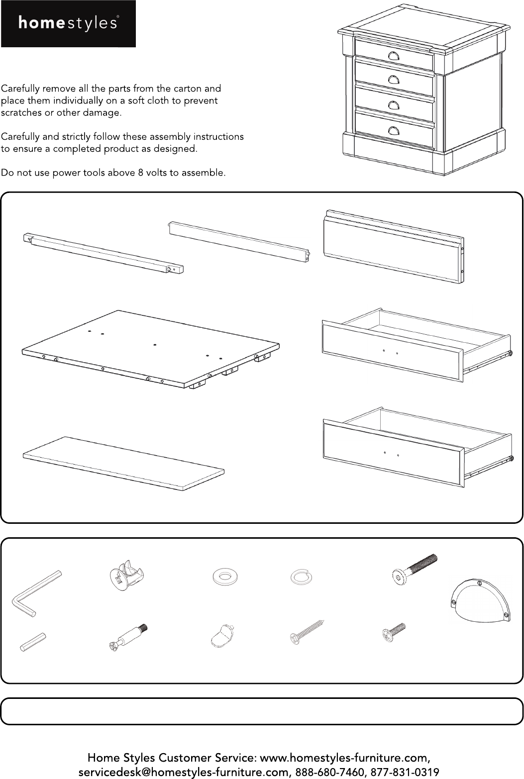
20 05520 0923 Storage Island IMPORTANT Part List B. Rail 2 pcs. C. Rail 3 pcs. F. Plinth 2 pcs. E. Bottom 1 pc. J. Drawer 1 pc. I. Shelf 3 pcs. K. Drawer 3 pcs. Refer to later page(s) of these instructions for drawer assembly. Hardware List Hex Wrench 1 pc. Cam Lock 30 pcs. (+6 extra) Flat Washer 12 pcs. (+1 extra) Spring Washer 12 pcs. (+1 extra) M6x32 Head Cap Bolt 12 pcs. (+1 extra) Handle 4 pcs. Small Hex Wrench 1 pc. Cam Lock Screw 30 pcs. (+2 extra) Adjustable Pin 12 pcs.
Assembly Instructions 2/8 IMPORTANT Use a soft cloth between these parts and the floor. Do not use power tools above 8 volts to assemble. Do not tighten all the bolts until each part is properly assembled. The unit must be level to work properly. Use the included adjustable levelers to level. Keep Hex Wrench as the bolts may need to be tightened in the future.
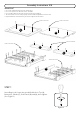
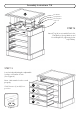
Assembly Instructions 3/8 STEP 2 D F Attach Back Panel (D) to Bottom (E) with Cam Locks. (See Figure 2) Attach Plinths (F) to unit with Cam Locks. E F Cam Lock Figure 2 Wood Screw Flat Washer Spring Washer STEP 3 B Head Cap Bolt Attach unit form Step 2 to Side Panel (H) with Flat Washers, Spring Washers, Head Cap Bolts and Cam Locks, tightening bolts only halfway. (See Figure 3) B C C Attach Rails (B) and (C) to unit with Cam Locks and Wood Screws.
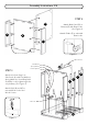
Assembly Instructions 4/8 Wood Screw G STEP 4 Attach Side Panel (G) to unit with Cam Locks, Flat Washers, Spring Washers, Head Cap Bolts and Wood Screws, tightening bolts only halfway. Turn unit to it’s upright position. Cam Lock Flat Washer Spring Washer Head Cap Bolt Adjustable Pin STEP 5 I I I Insert Adjustable Pins into side panels at desired level. Place Shelves (I) into position.
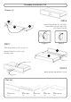
Assembly Instructions 5/8 Drawer (J) STEP 6 J4 Attach Drawer Sides (J3) and (J4) to Drawer Back (J2), then flip Locks. (See Figures 4 and 5) J3 J2 Lock Figure 4 STEP 7 Figure 5 Slide Drawer Bottom (J5) into groove. J1 Attach Drawer Front (J1) to unit, then flip Locks. J5 Lock Machine Screw STEP 8 Attach Handle with Machine Screw. Handle Part List J1. Drawer Front 1 pc. J2. Drawer Back 1 pc. J3. Drawer Side 1 pc. J4. Drawer Side 1 pc. J5. Drawer Bottom 1 pc.
Assembly Instructions 6/8 Drawer (K) K4 K3 K2 STEP 9 Lock Attach Drawer Sides (K3) and (K4) to Drawer Back (K2), then flip Locks. STEP 10 K1 Slide Drawer Bottom (K5) into groove. Attach Drawer Front (K1) to unit, then flip Locks. K5 Lock Machine Screw STEP 11 Attach Handle with Machine Screw. Handle Part List K1. Drawer Front 3 pcs. K2. Drawer Back 3 pcs. K3. Drawer Side 3 pcs. K4. Drawer Side 3 pcs. K5. Drawer Bottom 3 pcs.
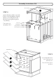
Assembly Instructions 7/8 A Flat Washer Spring Washer Head Cap Bolt Cam Lock STEP 12 Attach Top (A) to unit with Cam Locks Flat Washer, Spring Washer and Head Cap Bolts, tightening bolts only halfway. STEP 13 Level unit by adjusting the adjustable levelers on bottom of unit. (See Figure 6) Note: Unit must be level to work properly. Slide Drawers (J) and (K) into position.
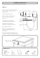
Assembly Instructions 8/8 Per regulatory requirements, a Tip-over Restraint is included. Follow Step 14 to install it. STEP 14 Drill a 3/16” hole 1/2” deep 1” below top of unit in middle of side panel that is against a wall. Anchor in wall Bracket on wall Wall Screw 3/8” wall hole 3/16” hole in side panel of unit Wood Screw Place unit at desired location. Drill a 3/8” hole in wall in-line with 3/16” hole drilled in side panel. Tie end Move unit.
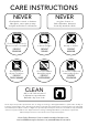
CARE INSTRUCTIONS NEVER NEVER use glass cleaners on finished furniture. Ammonia chemically attacks the finish. allow liquids to remain on furniture. Absorption causes parts to warp and split and finishes to delaminate. Do not use power tools above 8 volts to assemble. Do not place in direct sunlight. Do not write directly on surface. PREVENT CRACKING PREVENT FADING PREVENT MARKING Do not place hot objects on surface. Do not use rubber based placemats. Do not use commercial waxes and polishes.