
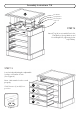
Assembly Instructions 3


Assembly Instructions 8/8
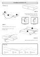
Hardware List
Anchor
1 pc. (+1 extra)
Tipover Restraint
1 pc. (+1 extra)
M3.5x38
Wall Screw
1 pc. (+1 extra)
M3x16
Wood Screw
1 pc. (+1 extra)
Bracket
2 pcs. (+1 extra)
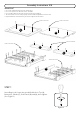
STEP 14
Drill a 3/16” hole 1/2” deep 1” below top
of unit in middle of side panel that is
against a wall.
Place unit at desired location.
Drill a 3/8” hole in wall in-line with
3/16” hole drilled in side panel.
Move unit.
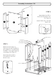
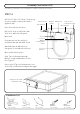
Insert Anchor into the wall hole
and attach Bracket with Wall Screw.
Attach Bracket at drilled hole in
side panel of unit with Wood Screw.
Move unit back into place.
Slide Tip-over Restraint through
Bracket on wall and Bracket on unit.
(See Figure 7)
Put tie end of Tip-over Restraint into lock
end of Tip-over Restraint and pull until tight.
Drill 3/8” hole in wall
Side Panel of unit
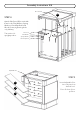
Per regulatory requirements, a Tip-over Restraint is included. Follow Step 14 to install it.
Figure 7
Wood Screw
Wall Screw
Bracket
on wall
Anchor in wall
3/8” wall hole
3/16” hole in
side panel of unit
Tie end
Lock end
Bracket
on side panel
of unit
Tip-over
Restraint