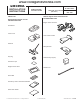
www.collegehillshonda.com Accessory INSTALLATION INSTRUCTIONS PARTS LIST Remote Engine Starter Unit Kit P/N 08E91-E22-100B Application Publications No.
www.collegehillshonda.
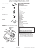
www.collegehillshonda.com Setting the Control Unit 3. Get the control unit. Using a small flat-tip screwdriver, adjust the switches on the control unit to the locations shown. Using a isopropyl alcohol on a shop towel, clean the area where the protective tape will attach. Attach the protective tape to the control unit over the switches. Removing the vehicle parts NOTE: • The switches must be selected before the control unit is plugged in. 4.
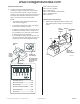
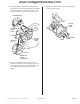
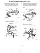
www.collegehillshonda.com 4. Using the key, unlock the opener. 7. 5. Remove the left front door sill trim (two retaining tabs, five clips, and three hooks). If equipped, remove the driver’s dashboard under cover (turn the knob counterclockwise, and release two clips and pin). 3 HOOKS 5 CLIPS PIN 2 RETAINING TABS 2 CLIPS DRIVER’S DASHBOARD UNDER COVER KNOB FRONT 5202112T 8. LEFT FRONT DOOR SILL TRIM 6. 5202200T Remove the driver’s dashboard lower cover (eight clips).
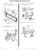
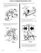
www.collegehillshonda.com 9. Lower the tilt lever, and pull the steering wheel toward you. Insert a long blade flat-tip screwdriver along the guide of the column lower cover, and pry the retaining tab of the column upper cover. 11. Remove the column lower cover (two self-tapping screws and one screw). 2 RETAINING TABS Push.
www.collegehillshonda.com 12. If equipped, use a small flat-tip screwdriver to remove the left and right lens from the map light console (four retaining tabs for each lens). Remove the two bolts, and then release the map light console. 14. Remove the cap from the left sunvisor (four retaining tabs). CONNECTOR 4 RETAINING TABS FRONT MAP LIGHT CONSOLE LEFT SUNVISOR CAP TORX SCREW 4 RETAINING LENS TABS 5217030T 15. Remove the left sunvisor (two T25 Torx screws, and unplug the vehicle connectors).
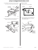
www.collegehillshonda.com 18. Pull away the weatherstrip from the left front pillar trim. Remove the left front pillar trim (two clips). LEFT FRONT PILLAR TRIM Installing the Antenna 20. Using scissors, cut out the template. SCISSORS TEMPLATE 2 CLIPS Cut out. WEATHERSTRIP 6D01203T 5202100T 19. Remove the clip from the left front pillar trim, and install a new clip on the left front pillar trim. 21.
www.collegehillshonda.com 22. Using two pairs of needle-nose pliers, bend the antenna plate according to the illustration and measurement shown. 23. Measure the antenna cable as shown. Attach the three foam cushion tapes to the antenna cable in the measurement shown. ANTENNA CABLE ANTENNA ANTENNA FOAM CUSHION TAPE 15 mm (0.6 in.) 360 mm (14 in.) 8 mm (0.3 in.) 30 mm (1.2 in.) 30 mm (1.2 in.) 6D01240T 24. Using isopropyl alcohol on a shop towel, clean the area where the antenna will attach.
www.collegehillshonda.com 27. Route the antenna cable under the roof liner towards the driver’s side of vehicle, and down along the vehicle harness. Be careful not to crease the roof liner. 29. Using isopropyl alcohol on a shop towel, clean the areas where the foam cushion tape will attach. Under the roof liner, secure the antenna cable to the roof panel with the two foam cushion tapes (cut one foam cushion tape in half) in the areas shown.
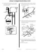
www.collegehillshonda.com 31. Secure the antenna cable to the vehicle harness with a wire tie. Secure the wire tie between the vehicle harness branching points. WIRE TIE VEHICLE HARNESS Routing the Engine Starter Harness 33. Attach the 3 A fuse labels to the engine starter harness fuse case, and the 40 A fuse labels to the fuse block.
www.collegehillshonda.com 35. Route the engine starter harness 7-pin connectors up the steering column and to the ignition switch. Unplug the white vehicle 7-pin connector. Plug the white engine starter harness 7-pin connectors into the white vehicle 7-pin connectors. 37. Disconnect the vehicle 8-pin connector on the rear of the wiper switch and plug the engine starter harness 8-pin connector into the vehicle 8-pin connector.
www.collegehillshonda.com 39. Wrap the vehicle 7-pin connector with one foam cushion tape, then place the vehicle 7-pin connector into the gap of the column. VEHICLE 7-PIN CONNECTOR (brown) (Squeeze into this area.) 42. At the right of the steering shaft, locate the sub joint box. Using a small flat-tip screwdriver, unplug the vehicle 6-pin connector from the sub joint box. Plug the engine starter harness 6-pin connectors into the vehicle 6-pin connector and the subjoint box.
www.collegehillshonda.com 45. With driver's dashboard under cover: Measure the indicated dimension on the instrument panel and mark with a felt-tip pen and a center punch. 46. Secure the engine starter harness to the vehicle harness using a wire tie. INSTRUMENT PANEL • With driver's dashboard under cover: Secure in the hole you made in the instrument panel. • Without driver's dashboard under cover: Secure through the existing hole for under cover securing. WIRE TIE View from below 12 mm (0.5 in.
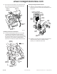
www.collegehillshonda.com 48. Disconnect the vehicle 42-pin, 4-pin and 2-pin connectors. 49. Plug the engine starter harness 4-pin and 2-pin connectors into the fuse box. VEHICLE 4-PIN CONNECTOR VEHICLE 2-PIN CONNECTOR VEHICLE 42-PIN CONNECTOR FUSE BOX NOTICE Check that the engine starter harness 4-pin and 2-pin connectors are connected to the fuse box and they are locked securely. Loosely connected connectors can cause engine stall during driving.
www.collegehillshonda.com 51. Connect the engine starter harness 18-pin connectors with each other and secure them with a wire tie to the vehicle harness. 53. Install the clip from the engine starter harness to the fuse box bracket behind the fuse box. GROUND BOLT (Reuse.) ENGINE STARTER HARNESS 18-PIN CONNECTORS FRONT ENGINE STARTER HARNESS GROUND TERMINAL ENGINE STARTER CLIP HARNESS WIRE TIE VEHICLE HARNESS 6D01331T 52.
www.collegehillshonda.com 58. Using isopropyl alcohol on a shop towel, clean the area where the engine starter label will attach. Installing the Control Unit 55. Connect the antenna cable terminal and the engine starter harness 18-pin connector to the control unit. HOOD ANTENNA CABLE TERMINAL (Connect first.) ADHESIVE BACKING ENGINE STARTER LABEL 6D01421T FRONT CONTROL UNIT CONTROL UNIT BRACKET ENGINE STARTER HARNESS 18-PIN CONNECTOR 59. Attach the engine starter label to the back of the hood.
www.collegehillshonda.com REMOTE ENGINE STARTER REGISTRATION 5. 1. Acquire the PCM code from ISIS. 2. Connect the HDS tester to the OBD II data link connector, then turn the ignition switch to the ON (II) position. 3. Start the HDS, and click the car icon. Select Honda Systems, then click the check button. CAR ICON Select “Honda Systems.” CHECK BUTTON 752503AS 6. Select R/C ENG STARTER and click the check button. 752501AS 4.
www.collegehillshonda.com 7. A REMARKS message will display. Click the check button. 9. “REMARKS” message The following message will display: Obtain PCMcode (IMMOBILIZER PCM CODE) from iN. This vehicle’s VIN will be required to obtain the password. (USA). Click the check button. “Obtain PCM-code" message CHECK BUTTON 752505AS CHECK BUTTON 8. Select REGISTER REMOTE CONTROL ENGINE STARTER UNIT, then click the check button. 752507AS 10. Input the PCM Code, then click the check button.
www.collegehillshonda.com 11. The following message will display: The registration of the Remote Control Engine Starter Unit has been completed. Click the check button. "Registration" message CHECK BUTTON 752510AS 12. The following message will display: Check that the engine can be started by the Transmitter. Click the check button. “Check that the engine can be started by the Transmitter” CHECK BUTTON 752511AS 13. Perform the function check on page 21, then disconnect the HDS.
www.collegehillshonda.com FUNCTION CHECK Operating Conditions • The hood is closed. • Shift lever is in Park. • The key is not in the ignition switch. • All doors and trunk are closed and locked. Inspection 1. Within 1 second, press the command button and then the start button on the transmitter. The engine should start if all operating conditions are met. Does the engine start? Yes - Operation is normal. No: • Make sure all operating conditions are met.