The engine exhaust from this product contains chemicals known to the State of California to cause cancer, birth defects or other reproductive harm.
Thank you for purchasing a Honda tiller. We want to help you get the best results from your new tiller and to operate it safely. This manual contains the information on how to do that; please read it carefully. This owner’s manual describes the operation and maintenance tillers: FR650 and FR750 The illustrations in this manual are based on: FR750 of HONDA All information in this publication is based on the latest product information available at the time of printing. Honda Motor Co., Ltd.
CONTENTS 1. SAFETY INFORMATION .......................................................................... Safety label locations ............................................................................. Safety information .................................................................................. 2. COMPONENT IDENTIFICATION.. ............................................................ 3. PRE-OPERATION CHECK ...................................................................... Engine oil .......
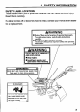
1. SAFETY INFORMATION SAFETY LABEL LOCATIONS These labels warn you of potential hazards that can cause serious injury. Read them carefully. If a label comes off or becomes hard to read, contact your Honda tiller dealer for a replacement. A\A/APhlIlU~ n Rotary Tillers can be hazardous if operated improperly. t To avoid serious injury, read all safety instructions carefully. W Read Owner’s Manual before operation. The Owner’s Manual has important safety and operation information.
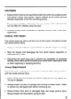
SAFETY INFORMATION Most accidents with tillers can be prevented if you follow all instructions in this manual and on the tiller. The most common hazards are discussed below and on the following pages, along with the best ways to protect yourself and others. Operator Responsibility l Keep the tiller in good operating condition. Operating a tiller in poor or questionable condition could result in serious injury. l Be sure all safety devices are in working order and warning labels are in place.
Child Safety l l l Keep children indoors and supervised at all times when any outdoor power equipment is being used nearby. Young children move quickly and are attracted especially to the tiller and tilling activity. Never assume children will remain where you last saw them. Be alert and turn the tiller off if children enter the area. Children should never be allowed to operate the tiller, even under adult supervision. Rotating Tines Hazard The rotating tines are sharp and they turn at high speed.
Fire and Burn Hazard Gasoline is extremely flammable, and gasoline vapor can explode. Use extreme care when handling gasoline. Keep gasoline out of reach of children. l l l l l Refuel in a well-ventilated area with the engine stopped. Allow the engine to cool before refueling. Fuel vapor or spilled fuel may ignite. The engine and the exhaust system become very hot during operation and remain hot for a while after stopping.
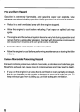
Operation l l l l on a Slope When tilling on slopes, keep the fuel tank less than half full to minimize fuel spillage. Till across the slope (At equally spaced intervals) rather than up and down it. Be very careful when changing the direction of the tiller on a slope. Do not use the tiller on a slope of more than 10”. The maximum safe grade angle shown is for reference purpose only and should be determined according to the type of the soil.
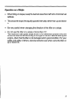
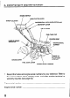
2. COMPONENT IDENTIFICATION ENGINE SWITCH MAIN CLUTCH THROTTLE LEVER LEVER \ / LOCK LEVER (FR750 only) /DIFFERENTIAL GEARSHIFT LEVER FUEL TANK CAP STARTER GRIP HANDLE HEIGHT ADJUSTER CHOKE LEVER FUEL COCK Llh’ER *FRAME * Record the frame and engine serial numbers for your reference. Refer to the serial numbers when ordering parts, and when making technical or warranty inquiries (see page 62).
SPARK PLUG MUFFLE ROTARY TINES 9
3. PRE-OPERATION CHECK ENGINE OIL 1. Place the tiller on a level surface. 2. Remove the oil filler cap and wipe the dipstick clean. 3. Insert the dipstick into the oil filler neck, but do not screw it in. 4. If the level is low, fill to the top of the oil filler neck with the recommended oil. Running damage. the engine with a low oil level will cause serious engine Use 4-stroke motor oil that meets or exceeds the requirements for API service classification SF or SG.
TRANSMISSION OIL Place the tiller on a level surface and remove the oil filler cap. The oil should be level with the lower edge of the oil filler hole. If the oil level is low, add the same motor oil that is recommended for the engine (see page 10). AIR CLEANER Remove the cover and inspect the air filter elements. Clean them if necessary (see page 37). Operating the engine with no air filter, or a damaged air filter, will cause rapid engine wear.
FUEL Refueling Remove the fuel tank filler cap, and check if the fuel is up to the level mark. If the fuel level is low, refill with regular gasoline up to the level mark. Fuel tank capacity: Gasoline is highly flammable You can be burned l l l 2.6 I? (0.69 US gal, 0.57 Imp gal) or seriously and explosive. injured when handling fuel. Stop the engine and keep heat, sparks, and flames away. Handle fuel only outdoors. Wipe up spills immediately.
Fuel Recommendations Use unleaded gasoline with a pump octane rating of 86 or higher. This engine is certified to operate on unleaded gasoline. Unleaded gasoline produces fewer engine and spark plug deposits and extends exhaust system life. Never use stale or contaminated gasoline or an oil/gasoline getting dirt or water in the fuel tank. Occasionally you may hear a light “spark knock” or “pinging” mixture. Avoid (metallic rapping noise) while operating under heavy loads.
Oxygenated Fuels Some conventional gasolines are being blended with alcohol or an ether compound. These gasolines are collectively referred to as oxygenated fuels. To meet clean air standards, some areas of the United States and Canada use oxygenated fuels to help reduce emissions. If you use an oxygenated fuel, be sure it is unleaded and meets the minimum octane rating requirement. Before using an oxygenated fuel, try to confirm the fuel’s contents.
TIRE PRESSURE Check tire pressure. carrying capacity. Improper inflation can reduce both tire life and load TIRE SIZE: 3.50-7 TIRE PRESSURE: 120 kPa (1.2 kg/cm2, 17.1 psi) LOCK PIN CLEVIS PIN TIRE VALVE- -xv WHEEL CLEVIS PIN Make sure the clevis pin and lock pin are securely installed.
TINES AND FASTENERS With the engine stopped, and the tiller on level ground, inspect the tines and check for loose nuts and bolts. Wear heavy gloves to protect your hands. Replace worn, bent, or damaged tines. Securely tighten loose nuts and bolts. Be sure to check the tightness of fasteners at the following places: Tine cover and transmission case l Tine cover and side cover l Tine cover and rear shield l Stiffening plate and tine hub l PLATE TINE COVER I\YM TRANSMISSION 16 CA / SIDE d0VER .
4. STARTING THE ENGINE Start the engine outdoors. If you run the engine in an area that is confined, or even partially enclosed, the air can become contaminated with a dangerous amount of exhaust gas. Exhaust contains poisonous carbon monoxide, a colorless and odorless gas. Breathing exhaust can cause loss of consciousness and may lead to death. To keep exhaust gas from building up, provide adequate ventilation. 1. Turn the fuel valve lever to the ON position.
4. Turn the engine switch to the ON position. ON INE SWITCH 5. In cold weather and when the engine is cold, move the choke lever to the CLOSE position., NOTE: Do not use the choke if the engine is warm or the air temperature is high. 6. Move the throttle lever about 30 degrees from the extreme right (idle position).
7. Pull the starter grip lightly until resistance is felt, then pull briskly. Do not allow the starter grip to snap back against the engine. Return it gently to prevent damage to the starter. 8. Let the engine warm up for several minutes. If the choke lever has been moved to the CLOSE position, return it gradually to the OPEN position as the engine warms up. CHOKE LEVER 9. Adjust the throttle lever so that the engine speed is suitable. ,’ ,, ,’ I ,’ ,’ ,’ ,’ ,’ ,,** ,’ ,’ //L H...
5. TILLER OPERATION HANDLEBAR HEIGHT ADJUSTMENT Handlebar height can be adjusted to four positions to suit operator height and working conditions. Select the height that provides the most comfortable operating position. Before adjusting the handlebar, place the tiller on firm, level ground and stop the engine. 1. Unscrew the height adjusting lever, and remove the height adjusting bolt. 2. Adjust the handlebar to the desired height. 3.
TILLING DEPTH ADJUSTMENT To adjust the tilling depth, loosen the locking bolt and move the drag bar up or down. Before adjusting the drag bar, place the tiller on firm, level ground and stop the engine. Use the gauge lines and indentations on the drag bar to adjust the tilling depth. Line up the top of the bar holder with a gauge line, and tighten the locking bolt. The drag bar should always be used when tilling. It enables you to compensate for the hardness of the soil.
GEAR SELECTION Return the throttle lever to the idle position and disengage the main clutch before moving the gearshift lever. Avoid using excessive force on the gearshift lever. Gearshift lever Select a gear position in accordance with the contents of the Gear Selection Table. Gear Selection l l l Always operate the gearshift lever after the main clutch has been disengaged.
MAIN CLUTCH OPERATION The tiller can be run or stopped by operating the main clutch lever. When operating the tiller, always walk behind and in the center of the tiller and hold the handlebar with both hands. If the tiller becomes unbalanced, an unforeseen accident may occur. Squeeze main clutch lever + clutch engages and tiller runs MAIN CLUTCH LEVER Release main clutch lever * clutch disengages and tiller stops NOTE: Operate the main clutch lever smoothly.
DIFFERENTIAL LOCK OPERATION (FR750 only) For normal operation set the differential lock lever in the UNLOCK position. This improves the tiller’s turning ability. When the ground is soft and one wheel tends to slip or when only one side is to be tilled, set the differential lock lever in the LOCK position. This improves the tiller’s forward movement ability. Move the differential lock lever after the clutch lever has been disengaged and the tiller has stopped.
TURNING (when moving) Turn the tiller with the engine speed lowered. (FR650) Turn the tiller with the differential lock lever in the UNLOCK position and the engine speed lowered. (FR750) l l Turning the tiller during high-speed operation causes the tiller to turn abruptly and become unstable, resulting in injury or accident. Do not turn the tiller when it is moving uphill or downhill.
TILLING WORK Tilling deeply at first may cause the tiller to lurch forward If a stone or hard object hits against the tines while handlebar may lift up and the tiller may lurch forward caution must therefore be exercised. suddenly. tilling, the suddenly; When operating the tiller, always walk behind and in the center of the tiller and hold the handlebar with both hands. If the tiller becomes unbalanced, an unforeseen accident may occur.
HIGH ALTITUDE OPERATION At high altitude, the standard air-fuel mixture will be too rich. Performance will decrease, and fuel consumption will increase. A very rich mixture will also foul the spark plug and cause hard starting. High altitude performance can be improved by specific modifications to the carburetor. If you always operate your tiller at altitudes above 6,OOOfeet (1,800 meters), have your servicing dealer perform this carburetor modification.
6. STOPPING THE ENGINE 1. Release the main clutch lever to disengage the clutch. MAIN CLUTCH LEVER 2. Move the throttle lever toward the ‘I” position to reduce the engine speed. 3. Set the gearshift lever in the NEUTRAL position.
4. Turn the’engine switch to the OFF position to stop engine. OFF ENGINE sWlTCH 5. Turn the fuel valve lever OFF. FUEL VALVE LEVER NOTE: To stop the engine in an emergency, engine switch OFF.
7. TRANSPORTING The engine and exhaust system become hot during operation and remain hot for a while after stopping. Contact with hot engine components can cause burns and can ignite some materials. Avoid touching the engine or exhaust system for at least 15 minutes after the engine has stopped. Allow the engine to cool before transporting the tiller. Before Loading Turn the fuel valve lever to the OFF position.
8. MAINTENANCE THE IMPORTANCE OF MAINTENANCE Good maintenance is essential for safe, economical, and trouble-free operation. It will also help reduce air pollution. Improper maintenance, or failure to correct a problem before operation, can cause a malfunction in which you can be seriously hurt or killed. Always follow the inspection and maintenance schedules in this owner’s manual.
MAINTENANCE SAFETY Some of the most important safety precautions follow. However, we cannot warn you of every conceivable hazard that can arise in performing maintenance. Only you can decide whether or not you should perform a given task. Failure to properly follow maintenance instructions cause you to be seriously hurt or killed. Always follow the procedures and precautions and precautions in the owner’s can manual.
EMISSION CONTROL SYSTEM Source of Emissions The combustion process produces carbon monoxide, oxides of nitrogen, and hydrocarbons. Control of hydrocarbons and oxides of nitrogen is very important because, under certain conditions, they react to form photochemical smog when subjected to sunlight. Carbon monoxide does not react in the same way, but it is toxic. Honda utilizes lean carburetor settings and other systems to reduce the emissions of carbon monoxide, oxides of nitrogen, and hydrocarbons. The U.S.
Replacement Parts The emission control systems on your Honda engine were designed, built, and certified to conform with EPA and California emission regulations. We recommend the use of genuine Honda parts whenever you have maintenance done. These original-design replacement parts are manufactured to the same standards as the original parts, so you can be confident of their performance.
MAINTENANCE SCHEDULE REGULAR SERVICE PERIOD (3) ITEM Perform at every indicated month or operating interval, whichever comes first. EACH USE Every 2 years (2) J NOTE: l (1) (2) (3) (4): (5): Emission related items. Service more frequently when used in dusty areas. These items should be serviced by an authorized Honda tiller dealer, unless the owner has the proper tools and is mechanically proficient. See the Honda Shop Manual.
ENGINE OIL CHANGE OIL CAPACITY: 0.6 I?(0.6 US qt, 0.5 Imp qt) Drain the oil while the engine is warm to assure rapid and complete draining. ENGINE OIL FILLER CAP/DIPSTICK 1. Place a suitable container in front of the tiller to catch the used oil. 2. Remove the oil filler cap/dipstick and drain bolt. 3. Tilt the tiller forward and allow all of the oil to drain. OIL DRAIN BOLT 4. Reinstall and tighten the oil drain bolt. Refill with the recommended oil (page 10) to the top of the oil filler neck.
AIR CLEANER SERVICE A dirty air filter will restrict air flow to the carburetor, reducing engine performance. If you operate the tiller in very dusty areas, clean the air filter more often than specified in the MAINTENANCE SCHEDULE. Operating the engine with no air filter, or a damaged air filter, will cause rapid engine wear. 1. Remove the cover wing nut, then remove the air cleaner cover. 2. Remove thefilterwing nut, then remove and separate the air filter elements.
3. Foam element: Clean in warm soapy water, rinse and allow to dry thoroughly. Or clean in nonflammable solvent and allow to dry. Dip the element in clean engine oil and squeeze out all excess oil. The engine will smoke during initial running if too much oil is left in the foam. 4 Paper element: Tap the element several times on a hard surface to remove excess dirt, or blow compressed air [not exceeding 207 kPa (30 psi)] through the filter from the inside.
SEDIMENT CUP CLEANING 1. Turn the fuel valve to the OFF position. 2. Remove the sediment cup with a 10 mm wrench. 3. Empty the sediment cup, and wash it in nonflammable solvent. 4. Inspect and reinstall the O-ring. Replace the O-ring if it is damaged. 5. Install the sediment cup, and tighten it securely. 6. Turn the fuel valve to the ON position, and check for leaks. Gasoline is extremely flammable, and gasoline vapor can explode. Turn the fuel valve to the OFF position after servicing the sediment cup.
SPARK PLUG SERVICE Recommended spark plug: BPR5ES (NGK), WlGEPR-U (DENSO) Spark plugs of the wrong dimensions damage. or heat range can cause engine For good performance, the spark plug must be properly gapped and free of deposits. If the engine has been running, the muffler will be very hot. Be careful not to touch the muffler. 1. Clean any dirt from around the spark plug base. 2. Remove the spark plug cap. Use a 13/l 6 inch spark plug wrench to remove the spark plug.
3. Visually inspect the spark plug. Discard it if the insulator is cracked or chipped. Clean the spark plug with a wire brush if it is to be reused. 4. Measure the spark plug electrode gap with a feeler gauge. Correct the gap as necessary by carefully bending the side electrode. The gap should be: 0.70 - 0.80 mm (0.028 - 0.031 in) 0.70 - 0.80 mm (0.028 - 0.031 in) 5. Install the spark plug carefully, by hand, to avoid cross-threading. 6.
SPARK ARRESTER MAINTENANCE (optional equipment) The engine in your tiller is not factory-equipped with a spark arrester. In some areas, it is illegal to operate an engine without a spark arrester. Check local laws and regulations. A spark arrester is available from authorized Honda servicing dealers. The spark arrester must be serviced every 100 hours to keep it functioning as designed. If the engine has been running, the muffler will be very hot.
5. Use a brush to remove carbon deposits from the spark arrester screen. Be careful to avoid damaging the spark arrester screen. The spark arrester must be free of breaks and holes. Replace if necessary. SPARK ARRESTER SCREEN 6. Install the spark arrester and the muffler in the reverse order of disassembly.
THROTTLE CABLE ADJUSTMENT Check and adjustment should be made with the handlebar in the 2nd position from the bottom. 1. Loosen the lock nut and turn the adjuster until the free play in the throttle lever at the end of the lever is 5.0 - 10.0 mm (0.20 - 0.39 in). 2. After adjusting the free play, tighten the lock nut securely. 5-10mm (0.20 - 0.
MAIN CLUTCH CABLE ADJUSTMENT The main clutch cable must be adjusted properly before adjusting the drive belt. An improperly adjusted main clutch cable may cause the drive belt to slip on its pulleys, resulting in loss of power or premature wear or damage to the drive belt. Check and adjustment should be made with the handlebar in the 2nd position from the bottom. 1. Check the free play of the main clutch lever at the tip of the lever when the lever is released. Free play should be: 15.0 - 20.0 mm (0.59 - 0.
DIFFERENTIAL LOCK CABLE ADJUSTMENT (FR750 only) If the differential lock cable is not correctly adjusted, it may become impossible to operate the differential lock. Check and adjustment should be made with the handlebar in the 2nd position from the bottom. 1. With the differential lock in the UNLOCK position, adjust so that the end has the free play dimensions shown below. Free play: 1 - 4 mm (0.04 - 0.16 in) 2. Adjust by loosening the lock nut and turning the adjusting nut. 3.
DRIVE BELT ADJUSTMENT The drive belt must be inspected regularly for correct tension. If the drive belt slips on its pulleys, that will result in loss of power and premature wear or damage to the drive belt. Inspection 1. Adjust the clutch cable (refer to page 45). 2. Remove the belt cover. 3. Stop the engine, remove the spark plug cap, and set the clutch lever in the LOCK position.
Adjustment 1. Adjust by loosening the engine lock nuts and belt stopper lock nuts (2 nuts on front side) and moving the engine back and forth. If gap is smaller than the specified dimension: Move engine forward. If gap is larger than the specified dimension: Move engine rearward. BELT STOPPER (2 ENGINE LOCK NUT (4) NOTE: During adjustment, line up the groove of the engine-side pulley and that of the transmission-side pulley. If they are not aligned, the belt may come off or will wear prematurely.
3. Confirm that the gap between the belt and belt stopper (3 points) is within the dimensions shown in the figure, while the main clutch lever is squeezed. 4. Adjust if the gap is not within the dimensions shown. 5. Adjust by loosening the stopper lock nut and moving the stopper up or down. 6. After adjustment has been completed, fasten the nut securely. 7. Install the belt cover. After adjustment, be sure to reinstall the belt cover.
TINE INSPECTION AND REPLACEMENT Use genuine Honda replacement tines or their equivalent. Wear heavy gloves to protect your hands. m l l Perform the check or replacement and the engine stopped. work with the tiller on a level spot Place a wooden block under the rotary tine shaft to prevent tines from dropping. The inside and outside tines rotate in opposite directions. Be careful of the movement of the tines when checking or replacing the rotary part.
Inspection 1. Check for damaged, bent, or loose tines. If looseness or damage is found, tighten or replace the damaged tines. t 2. Check that the rotary tine shaft’s clevis pin is not missing or damaged. If necessary, replace with a new clevis pin and lock pin. NOTE: To prevent the clevis pin from falling out, insert the lock pin in the direction opposite to the direction of rotation of the tines. CLEVIS PIN FORWARD ‘LOCK DIRECTION PIN 3.
Installation Arrange the rotary tines as shown in the figure. If the arrangement or orientation is changed, vibration may be produced, and normal tilling operation may become impossible. Facing the forward direction, install right-side tines 1,2,5, and 7 and left-side tines A, B, E, and G so that they are facing inside, and install right-side tines 3, 4, and 6 and left-side tines C, D, and F so that they are facing outside. Right-side tines 4 and 7 and left-side tines D and G have longer tips.
While pushing the rotary tines in the direction of rotation and the opposite direction, fasten the nut securely. PUSH BOL DIRECTION OF ROTATION These points should make contact. When assembling the rotary tines and holders, the match marks have to be aligned. If they are incorrectly assembled, vibration will be produced. Assemble them according to the following procedure. Line up the match marks on the forward tine holder and the reverse tine holder and assemble.
9. STORAGE PREPARATION FOR STORAGE When the tiller will not be used for one month or longer, proper storage preparation will help to prevent rust and corrosion, and will make it easier to start the engine when the tiller is removed from storage. 1. Clean all surfaces of the tiller, including the area underneath the tine cover. Wear heavy gloves to protect your hands.
For storage of a month or longer, perform these additional steps: 3. Fill the fuel tank with fresh gasoline, and add a gasoline conditioner, such as HONDA FUEL STABILIZER, which is formulated to extend fuel storage life. Be sure the fuel tank is completely filled. If partially filled, air in the tank will promote fuel oxidation and deterioration, resulting in bad fuel that may cause hard starting. Deteriorated fuel may also clog carburetor passages, requiring carburetor repair or replacement.
For storage of two months or longer, perform these additional steps: Before storing the unit for an extended period: 4. Drain the fuel... a. With the fuel valve turned OFF, remove and empty the sediment cup. b. Turn the fuel valve ON and drain the gasoline in the fuel tank into a suitable container. c. Replace the sediment cup and tighten securely. d. Drain the carburetor by removing the drain knob. Drain the gasoline into a suitable Gasoline container.
5. Change the engine oil (page 36). 6. Lubricate the piston and cylinder a. Remove the spark plug (page 40) b. Pour a tablespoon of clean engine oil into the cylinder. Pull the starter rope several times to distribute the oil in the cylinder. Reinstall the spark plug. NOTE: While the spark plug is removed, inspect the plug, and clean, gap, or replace it if necessary. c. Pull the starter rope unit1 you feel resistance. This closes the valves, which helps to protect the cylinder from corrosion.
STORAGE Select a that use operated gasoline storage area away from appliances (water heater or clothes dryer) an open flame as a heat source. Power tools, and some battery toys, have electric motors that produce sparks that can ignite vapors. Gasoline is extremely flammable, and.gasoline careful to avoid open flames or sparks. vapor can explode. Be Avoid storing the tiller where it will be exposed to high humidity and dust. Place the tiller with its tines and wheels on a level surface.
10. TROUBLESHOOTING When the engine will not start; 1. Is there enough fuel? 2. Is the fuel valve ON? 3. Is the engine switch ON? 4. Is gasoline reaching the carburetor? To check, loosen the drain knob with the fuel valve on. Fuel should flow out freely. Retighten drain knob. If any fuel is spilled, make sure the area is dry before testing the spark plug or starting the engine. Spilled fuel or fuel vapor may ignite.
5. Is there a spark at the spark plug? a. Remove the spark plug cap. Clean any dirt from around the spark plug base, then remove the spark plug. b. Install the spark plug in the plug cap. c. Turn the engine switch on. d. Grounding the side electrode to any engine ground, pull the recoil starter to see if sparks jump across the gap. l l l Never hold the spark plug lead with wet hands while performing this test. Make sure that no fuel has been spilled the plug is not wet with fuel.
11. SPECIFICATIONS DIMENSIONS AND WEIGHT Model Power code product description FR650 FR750 FZBV FZCG 1,450 mm (57.1 in) 1 ,100 mm (43.3 in) 570 mm (22.4 in) 1,450 mm (57.1 in) 1 ,100 mm (43.3 in) 570 mm (22.4 in) 83 kg (183 Ibs) 88 kg (194 Ibs) Dimensions, (Length) (Height) (Width) Dry weight Tire size 3.50 - 7 1,200 mm (47.
12. WARRANTY SERVICE INFORMATION Honda power equipment dealership personnel are trained professionals. They should be able to answer any question you may have. If you encounter a problem that your dealer does not solve to your satisfaction, please discuss it with the dealership’s management. The Service Manager or General Manager can help. Almost all problems are solved in this way.
13. INDEX COMPONENT IDENTIFICATION ..................................................................... CONTENTS ...................................................................................................... MAINTENANCE ............................................................................................. Air cleaner service .................................................................................... Differential lock cable adjustment (FR750 only) ....................................
MEMO