SNOW BLOWER CAB Model #04700-V45-000AH ! IMPORTANT ! READ THIS ASSEMBLY MANUAL CAREFULLY AND KEEP FOR FUTURE REFERENCE. REMOVE THE VINYL COVER FOR TRANSPORT IN AN OPEN TRUCK OR TRAILER.
WARNING 1. This cab is designed to provide foul weather protection only. It does not provide protection from noise, exhaust fumes, chemicals or injury from collision, rollover or other accidents. 2. Do not operate machine in confined areas without proper ventilation. 3. Thoroughly check area of operation before using machine. 4. The cab adds height to the machine. Low tree limbs and other overhead structures that did not interfere with the operation of the machine before, may now be obstacles.
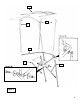
CARTON CONTENTS CAB MODEL #20157 PART # 20164 20158 20159 2226 4977 2389 4968 2230 20165 9672 20165 786 788 926 6654 2 4556 0730 60466 7929 20166 KEY # 1 2 3 4 5 6 7 8 9 10 QTY 1 1 1 2 2 1 1 1 1 1 1 6 2 2 2 2 4 12 2 4 2 DESCRIPTION CROSS BAR BRACKET, RH BRACKET, LH 1” “U” CLAMP FRONT POST HORIZONTAL BOW REAR BOW TOP FRAME FOAM PADDING 24” VINYL COVER HARDWARE PACKAGE (Contents Listed Below) 1/4” x 5/8” Bolt 1/4” x 3/4” Bolt 1/4” x 1” Bolt 1/4” x 1 3/4” Bolt 1/4” Lock Washers 1/4” x 1 1/4”” Fender Washer
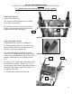
INSTALLATION INSTRUCTIONS COMPLETELY READ INSTRUCTIONS BEFORE INSTALLING THE CAB. The right side of the cab is determined from the operator’s position. Step 2; See Figure 2: Install The Cross Bar (1). A A. Remove the bolts at Reference A on both sides of the control panel. B. Place the Cross Bar on the control panel as shown. Insert two M6 x 20mm bolts with lock washers into the holes and tighten. 1 Figure 2 Step 3; See Figure 3 & 3A: Install Brackets (2 & 3) and “U” Clamps (4). A.
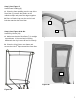
Step 4; See Figure 4: A. Attach the Horizontal Bow (6) and the Front Posts (5) to the Brackets (2 & 3) using two 1/4" x 3/4" bolts and locknuts (refer to detail A). B. Position the Front Posts on the inside of the assembly, the mounting tabs on the Horizontal Bow in the middle and the Brackets on the outside. C. Be sure the tops on the Front Posts point toward each other. D. Keep the bolt heads on the outside of the frame. Do not tighten the bolts at this time. Step 5; See Figure 4: A.
8 5 7 6 3 2 Figure 4 6
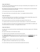
Step 5; See Figure 5: Install Foam Padding (9) A. Place the foam padding over the top of the Rear Bow (7) remove the plastic on the adhesive strips and press the edges together. B. Place a Plastic Cap over the end of each bolt that attaches the Rear Bow. 9 7 Step 6; See Figure 6A & 6B: Install Vinyl Cover (10) A. Make sure that the Rear Bow (7) is straight up and down. If the rear bow is leaning backwards the vinyl cover will not fit correctly. Figure 5 B.
LIMITED WARRANTY SNOW REMOVAL EQUIPMENT CABS COVERED BY WARRANTY ORIGINAL TRACTOR CAB CO., INC., (the "Company") warrants to the owner that each new product listed below is merchantable and free of defects in workmanship and material. During the warranty period, the dealer from whom the product was bought, or the Company, will provide, free of charge, parts and the shipping costs of parts necessary to correct any defect in workmanship and material.