I m! The generator is a potential source of electrical shock if misused. Do not expose the generator to moisture, rain or snow. Do not let the generator get wet, and do not operate it with wet hands.
Thank you for purchasing a Honda generator. We want to help you get the best results from you new generator and to operate it safely. This manual contains the information on how to do that; please read it carefully. This owner’s manual discribes the operation and maintenance of the EB3500X Honda Generator. All information in this publication is based on the latest product information available at the time of printing. Honda Motor Co., Ltd.
CONTENTS SAFETY ....................................................................................................... Safety Label Locations ......................................................................... Safety Information .................................................................................. .............................................................. COMPONENT IDENTIFICATION 4 .4 6 8 10 CONTROLS ..................................................................................
MAINTENANCE .................................................................................... Maintenance Schedule .. .................................................................... Tool Kit.. .............................................................................................. Engine Oil Change.. ............................................................................ Air Cleaner Service ............................................................................
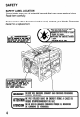
SAFETY SAFETY LABEL LOCATION These labels warn you of potential hazards that can cause serious injury. Read them carefully. If label comes off or becomes hard to read, contact your Honda Generator dealer for a replacement. I 4 RNlNG DONOTUSEINDOORS. EXHAUST GASCONTAINS POISONOUS CARBONMONOXIDE. ATTENTION NE PASUTILISER DANSUN ENDROIT FERMEA CAUSEDU RISOUE D’EMPOISONNEMENT DUGAL I ATENClON NOLOUSEENLUGARES CERRADOS POROUE EL MONOXIDE DE CARBON0 ES VENENOSO.
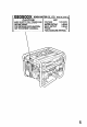
- EB3500X CAUTION ,TOR HONDAMO n BE SURE TO FILL CRANKCASE WITH RECOMMENDED _.-._--- OIL __BEFORE USING . FOR DETAILED EXPLANATION, SEE THE OWNER’S MANUAL. co.. LTD. AC VOLTAGE FREQUENCY RATED OUTPUT MAX. OUTPUT PHASE FUEL GASOLINE MADE IN JAPAN -24 12Ol24OV 60Hz 3.0kVA 3.
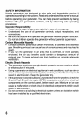
SAFETY INFORMATION Honda generators are designed to give safe and dependable service if operated according to instructions. Read and understand this owner’s manual before operating your generator. You can help prevent accidents by being familiar with your generator’s controls, and by observing safe operating procedures Operator Responsibility l l l Know how to stop the generator quickly in case of emergency. Understand the use of all generator controls, output receptacles, and connections.
Fire and Burn Hazards l l l l The exhaust system gets hot enough to ignite some materials. - Keep the generator at least 1 mater (3 feet) away from buildings and other equipme.nt during operation. - ,Do not enclose the generator in any structure. - Keep flammable materials away from the generator. The muffler becomes very hot during operation and remains hot for a while after stopping the engine. Be careful not to touch the muffler-while it is hot.
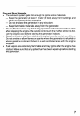
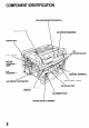
COMPONENT IDENTIFICATION VOLTAGE SELECTOR SWITCH ENGINE SWIT RECEPTACLES GROUND TERMINAL GFCI RECEPTACLE \ OIL FILLER CAP / AUTO-THROTTLE SWITCH n I OIL DRAIN PLUG ENGINE SERIAL NUMBER 8
FUEL TANK CAP FUEL METER SPARK CAP PLUG / OCCUP ANTS IGFCI) TEST RIECOlib ’ I FRiME SERIAL NUMBER MUFFLER l Record the engine and frame serial numbers for your future reference.
CONTROLS Engine Switch To start and stop the engine Switch position: OFF: To stop the engine. ON: To run the engine. ENGINE SWITCH Recoil Starter To start the engine, pull the starter grip lightly until resistance is felt, then pull briskly.. -1 Do not allow the starter to snap back against engine.Return it gently to prevent damage to the starter.
Fuel Valve The fuel valve is located between the fuel tank and carburetor. When the valve lever is in the ON position, fuel is allowed to flow from the fuel tank to the carburetor. Be sure to return the lever to OFF after stopping the engine. Choke Rod The choke is used to provide proper starting mixture when the engine is cold. It can be opened and closed by operating the choke rod manually. Pull the rod out toward CLOSED to enrich the mixture.
Circuit Breaker The circuit breaker will automatically switch OFF if there is a short circuit or a significant overload of the generator at the receptacle. If the circuit breaker is switched OFF automatically, check that the applicance is working properly and does not exceed the rated load capacity of the circuit before switching the circuit breaker ON again. The circuit breaker may be used to switch the generator power ON or OFF.
Auto-throttle System The auto-throttle system automatically reduces engine speed when all loads are turned off of or disconnected. When appliances are turned on or reconnected, the engine returns to the rated speed. AUTO: Recommended to minimize fuel consumption and further reduce noise levels when no load is applied to the generator. OFF: The auto-throttle system does not operate.
Ground Fault Circuit Interrupter (GFCI) Receptacle A Using the generator in rain, snow or near water can lead to w! death from electric shock. Keep the genetator dry. All of the 20 ampere 120 volt receptacles on the generator are protected by a Ground Fault Circuit Interrupter (GFCI) for protection against the hazards of ground fault currents.
INSPECTION Perform the tests below to ensure proper operation of the GFCI. Record your test on the GFCI test card provided on the generator. Before each use: If the generator is stored outdoors, unprotected from the weather, test the GFCI receptacle before each use as described in the monthly inspection. Monthly: Under normal operating conditions, perform the GFCI test monthly. 1. Unplug all appliances from the generator. 2. Start the engine. 3. Turn the circuit breaker ON. 4.
6. Press the RESET BUTTON - The RESET BUTTON should be flush with the test button. - If the RESET BUTTON is not flush with the TEST BUTTON. contact an authorized Honda generator dealer. 7. When the RESET BUTTON extends during operation: - Unplug all appliances from the GFCI protected receptacle. - Press the RESET BUTTON: IF THE GFCI CANNOT BE RESET: The GFCI is faulty. Contact an authorized Honda generator dealer. IF THE GFCI RESETS PROPERLY: Check the appliance or the power cord.
Voltage Selector Switch (Dual Voltage System) The voltage selector switches the main power carrying windings of the generator to produce “12OV ONLY” or “120/24OV”. If a 240V appliance is connected to the 4-prong receptacle, the switch must be in the “120/24OV” position. If a 12OV appliance ONLY is being connected to any of the 12OV 3-prong receptacles, select the “120V ONLY” position. The 12OV and 120/24OV receptacles can be used 120/24OV: simultaneously. 120V ONLY: ONLY the 12OV receptacles can be used.
GENERATOR USE Connections to a Building’s Electrical System Connections for standby power to a building’s electrical system must be made by a qualified electrician. The connection must isolate the generator power from utility power, and must comply with all applicable laws and electrical codes. Lw! Improper connections to a building’s electrical system can allow electrical current from the generator to backfeed into the utility lines.
AC Applications Before connecting l l l an appliance or power cord to the generator: Make sure that it is in good working order. Faulty appliances or power cords can create a potential for electrical shock. If an appliance begins to operate abnormally, becomes sluggish or stops suddenly, turn if off immediately. Disconnect the applicance, and determine whether the problem is the appliance, or if the rated load capacity of the generator has been exceeded.
AC Operation 1. Start the engine (refer to page 27). 2. Turn the voltage selector switch to either position. With the voltage selector switch in the “1201240 V” position, you can use the 120 V and 120/240 V receptacles simultaneously. If you are NOT using the 120/240 V receptacle, but require more power from the 120 V twist lock receptacle, then select the “120 V ONLY” position. 3. Switch ON the AC circuit breaker. 4. Plug in the appliance.
AC Receptacle Selection The generator has two separate main power producing circuits. These two circuits supply equal power to receptacles shown when the voltage selector switch is in the 120/240 V position. When two or more receptacles are used; prevent overloading the load between the two power circuits. by dividing The chart below shows the rated load in amperes that can be connected to each receptacle to balance the generator. The total rated ampere draw is 25.0 A.
Auto-throttle system With the switch in the AUTO position, engine speed is automatically reduced when ALL loads are turned OFF or disconnected. When appliances are turned ON or reconnected, the engine returns to rated speed. In the OFF position, the auto-throttle system does not operate. The auto-throttle system will not respond to electrical loads of less than 1 ampere. Turn the auto-throttle to the OFF position to operate loads of less than 1 amp.
High Altitude Operation At high altitude, the standard carburetor air-fuel mixture will be excessively rich. Performance will decrease, and fuel consumption will increase. High altitude performance can be improved by installing a smaller diameter main fuel jet in the carburetor and readjusting the pilot screw. If you always operate the engine at altitudes higher than 6,000 feet above sea level, have an authorized Honda generator dealer perform this carburetor modification.
PRE-OPERATION CHECK Engine oil (NoTlCEj Engine oil is a major factor affecting engine performance and service life. Non-detergent and 2-stroke engine oils will damage the engine and are not recommended. Check the oil level BEFORE EACH USE with the generator on a level surface with the engine stopped. Use Honda 4-stroke oil, or an equivalent high detergent, premium quality motor oil certified to meet or exceed U.S. automobile manufacturer’s requirements for Service T Classification SG, SF/CC, CD.
Fuel Recommendation 1. Check the fuel level gauge. 2. Refill the tank if the fuel level is low. Do not fill above the shoulder of the fuel strainer. Gasoline is extremely flammable and is explosive under certain conditions. Refuel in a well-ventilated area with the engine stopped. Do not smoke or allow flames or sparks in the area where the engine is refueled or where gasoline is stored. Do not overfill the fuel tank (there should be no fuel in the filler neck).
Occasionally you may hear light “spark knock” or “pinging” (metallic rapping noise) while operating under heavy loads. This is no cause for concern. If spark knock or pinging occurs at a steady engine speed, under normal load, change brands of gasoline. If spark knock or pinging persists, see an authorized Honda generator dealer. pmiEq Running the engine with persistent spark knock or pinging can cause engine damage.
Starting the Engine 1. Make sure that the AC circuit breaker is in the OFF position. The generator may be hard to start if a load is connected. 2. Turn the fuel valve to the ON position. 3. Pull the choke rod to the CLOSE position. 4. Make sure the auto-throttle switch is in the OFF position, or more time will be required for warm up. 5. Move the engine switch to the ON position. 6. Pull the starter grip until compression is felt, then pull briskly. piimq Do not allow the starter grip to snap back.
MAINTENANCE Periodic maintenance and adjustment is necessary to keep the generator in good operating condition. Perform the service and inspection at the intervals shown in the Maintenance schedule below. L m! Exhaust gas contains poisonous carbon monoxide. Shut off the engine before performing any maintenance. If the engine must be run, make sure the area is well ventilated. 1 NOTICE-1 Use only genuine HONDA parts or their equivalent for maintenance or repair.
Tool kit The tools supplied with the generator will help you to perform the owner maintenance procedures listed on the following page. Always keep this tool kit with the generator.
Engine oil change Drain the oil while the engine is warm to assure complete and rapid draining. 1. Remove the drain plug and sealing washer, oil filler cap, and drain the oil. 2. Install the drain plug and sealing washer. Tighten the plug securely. 3. Refill with the recommended oil (see page 24) and check the level. Oil capacity: 1 .l 1 (1.16 US qt, 0.97 Imp qt) OIL DRAIN PLUG UPPER LEVEL \ . 0 m! Used motor oil may cause skin cancer if repeatedly left in contact with the skin for prolonged periods.
Air cleaner service A dirty air cleaner will restrict air flow to the carburetor. To prevent carburetor malfunction, service the air cleaner regularly. Service more frequently when operating the generator in extremely dusty areas. Using gasoline or flammable solvent to clean the filter element can cause a fire or explosion. Use only soapy water or nonflammable solvent. m Never run the generator without the air cleaner. Rapid engine wear will result. AIR CLEANER COVER 1.
Fuel Sediment Cup Cleaning The sediment cup prevents dirt or water which may be in the fuel tank from entering the carburetor. If the engine has not been run for a long time, the sediment cup should be cleaned. 1. Turn the fuel valve to the OFF position. Remove the sediment cup, O-ring, and filter. 2. Clean the sediment cup, O-ring, and filer in nonflammable point solvent. 3. Reinstall the filter, O-ring, and sediment cup.
Spark Plug Service Recommended spark plugs: BPR5ES (NGK) WlGEPR-U (NIPPONDENSO) To ensure proper engine operation, the spark plug must be properly gapped and free of deposits. If the engine has been running, the muffler will be very hot. Be careful not to touch the muffler. 1. Remove the spark plug cap. 2. Clean any dirt from around the spark plug base. 3. Use the wrench supplied in the tool kit to remove the spark plug. PLUG CAP 4. Visually inspect the spark plug.
6. Check that the spark plug washer is in good condition, and thread the spark plug in by hand to prevent cross-threading. 7. After the spark plug in seated, tighten with a spark plug wrench to compress the washer. - If installing a new spark plug, tighten l/2 turn after the spark plug seats to compress the washer. If reinstalling a used spark plug, tighten l/8-1/4 turn after the spark plug seats to compress the washer. -The spark plug must be securely tightened.
TRANSPORTING/STORAGE When transporting the generator, turn the engine switch and the fuel valve OFF. Keep the generator level to prevent fuel spillage. Fuel vapor or spilled fuel may ignite. 1. m! Contact with a hot engine or exhaust system can cause serious burns or fires. Let the engine cool before transporting or storing the generator. Take care not to drop or strike the generator when transporting. heavy objects on the generator. Do not place Before storing the unit for an extended period: 1.
1. Drain the carburetor by loosening the drain screw. Drain the gasoline into a suitable container. Gasoline is extremely flammable and is explosive under certain conditions. Perform this task in a well ventilated area with the engine stopped. Do not smoke or allow flames or sparks in the area during this procedure. DRAI,N SCREW 2. Change the engine oil. (page 30) 3. Remove the spark plug, and pour about a tablespoon of clean engine oil into the cylinder.
TROUBLESHOOTING When the engine will not start: 71 NO -Retillthefuelfanh. Is there enough oil in NO the engine? I b Add the recommended oil. YES 7 Is there a spark from NO the spark plug? there is no spilled fuel around the spark plug. Spilled fuel may ignite. YES To check: 1) Remove the spark plug cap and clean any dirt frdm around the spark plug. 2) Remove the spark plug and install the sparkplug in the plug cap. 3) Set the plug side electrode on the cylinder head.
No electricity at the AC receptacles: I 38 DEFECTS
WIRING DIAGRAM
SPECIFICATIONS Dimensions Model EB3500X Power equipment description code EA6 Length x Width x Height 605 x 495 x 485 mm (23.8 x 19.5 x 19.1 in) Dry weight 62 kg (136.7 lb) Engine GX240Ki Model 4-stroke, overhead valve, single cylinder Engine type Disolacement (Bore x Stroke) Compression ratio 242 cc (14.8 cu in) [73 x 58 mm (2.9 x 2.3 in)] 8.2 : 1 3,600 r.p.m. Engine speed Forced air Cooling system Transistorized lanition svstem magneto 1 .l JZ(1.16 US qt, 0.
INSTALLATION OF OPTIONAL PARTS Hanger Kit Installation 8 x 16 mm FLANGE BOLT (4) HANGER 1. Position the hanger at the generator’s balance point, in the middle of the fuel tank. 2. Fit the end tabs of the hanger through the bracket slots, and bolt the brackets to the hanger.
4 Wheel Kit Installation 1. Install the four wheels on the axle shaft. 2. Install the assembly to the generator using four bolts and nuts. - Inside Shorter end WHEEL StOPPER NOTE: Install the shaft with wheel stopper facing engine side.
2 Wheel kit Installation 1. 2. 3. 4. Install the two wheels on the axle shaft. Install the axle assembly on the generator using four bolts and nuts. Install the two stands using four bolts and nuts. Install right and left handles on the generator upper frame using brackets and six bolts.
CUSTOMER SERVICE INFORMATION Honda power equipment dealership personnel are trained professionals. They should be able to answer any question you may have. If you encounter a problem that your dealer does not solve to your satisfaction, please discuss it with the dealership’s management. The Service Manager or General Manager can help. Almost all problems are solved in this way.
Current customer service contact information: United States, Puerto Rico, and U.S. Virgin Islands: Honda Power Equipment dealership personnel are trained professionals. They should be able to answer any question you may have. If you encounter a problem that your dealer does not solve to your satisfaction, please discuss it with the dealership's management. The Service Manager or General Manager can help. Almost all problems are solved in this way.
INDEX .............................................................. COMPONENT IDENTIFICATION CONTROLS ...................................... . ....................................................... Auto-throttle system ............................................................................ Choke Rod .......................................................................................... Circuit Breaker ....................................................................................
INDEX .................................................................................... SPEClFltiATlONS STARTING THE ENGINE/STOPPING THE ENGINE .............................. TRANSPORTING/STORAGE.. ................................................................ TROUBLESHOOTING ............................................................................ WIRING DIAGRAM.. ................................................................................
MEMO 47
MEMO 48