Thank you for purchasing a Honda tiller. This manual covers operation and maintenance of F401 and F501 tillers. All information in this publication is based on the latest product information available at the time of approval for printing. Honda Motor Co., Ltd. reserves the right to make without notice and without incurring any obligation. No part of this publication may be reproduced This manual is considered with the tiller if resold. a permanent without written at any time permission.
CONTENTS ....................................................... SAFETY INFORMATION ............................................. COMPONENT IDENTIFICATION PRE-OPERATION CHECK ...................................................... STARTING THE ENGINE ....................................................... TILLER OPERATION ............................................................. STOPPING THE ENGINE ....................................................... MAINTENANCE .......................................
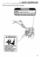
1. SAFETY Read all safety instructions before KEEP HANDS INFORMATION operating. AND FEET AWAY FROM TINES IGASOLINE IS FLAMMABLE AND EXPLOSIVE. STOP ENGINE.
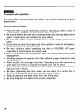
m To ensure safe operation- For your safety precautions: Operator l l . l l 0 l l l . l of others, pay special attention to these Responsibility Keep the tiller in good operating condition. Operating a tiller in poor or questionable condition could result in serious injury. Be sure all safety devices are in working order and warning labels are in place. These items are installed for your safety. Be sure the safety covers (V-belt cover, recoil starter cover) are in place.
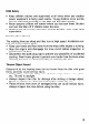
Child Safety l l l Keep children indoors and supervised at all times when any outdoor power equipment is being used nearby. Young children move quickly and are attracted especially to the tiller and the tilling activity. Never assume children will remain where you last saw them. Be alert and turn the tiller off if children enter the area. Children should never be allowed to operate the tiller, even under adult supervision.
Fire and Burn Hazard Gasoline is extremely flammable, and gasoline vapor can explode. Use extreme care when handling gasoline. Keep gasoline out of reach of children. l Refuel in a well-ventilated area with the engine stopped. l Allow the engine to co.01 before refueling. Fuel vapor or spilled fuel may ignite. l The engine and exhaust system become very hot during operation and remain hot for a while after stopping. Contact with hot engine components can cause burn injuries and can ignite some materials.
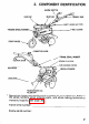
2. COMPONENT IDENTIFICATION ENGINE SWITCH & GAS CAP HANDLE BAR SHIFT LEVER (A2 TYPE) V-BELT COVER *ENGINE SERIAL NUMBER. FRONT WHEEL , THROTTLE LEVER *FRAME SERIAL NUMBER SPARK PLUG CAP AIR CLEANER COVER HANDLE HEIGHT ADJUSTER RECOIL STARTER TRANShSSION FILLER CAP OIL * Record the frame and engine serial numbers for your reference. Refer to the serial numbers when ordering parts, and when making technical or warranty inquiries (see page 30).
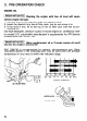
3. PRE-OPERATION ENGINE CHECK OIL 1 IMPORTANT NOTICE 1 R unning serious . engine the engine with low oil level will cause damage. 1. Remove the oil filler cap and wipe the dipstick clean. 2. Insert the dipstick into the oil filler neck, but do not screw it in. 3. If the level is low, fill to the top of the oil filler neck with the recommended oil. Use high-detergent, premium quality 4-stroke engine oil, certified to meet or exceed U.S.
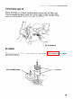
Transmission gear oil Place the tiller on a level surface and remove the oil filler cap. The oil should be level with the lower edge of the oil filler hole. Add recommended engine oil if the level is low. OIL FILLER HOLE Air cleaner Check cleaner for dirt or obstruction ing instructions.) AIR CLEANER COVER of elements.
GASOLINE Stop tank Fuel Fuel the engine. Remove the gas cap and check the fuel level. if the level is low. tank capacity: 0.9 P (0.95 US qt) tank capacity: F401 . . ...1.4 P (0.37 US Gal) F501 . . . . . 2.6 P (0.69 US Gal) Refill the Gasoline is extremely flammable, and gasoline vapor can explode. Use extreme care when handling gasoline. Keep gasoline out of reach of children. l Refuel in a well ventilated area with the engine stopped. Keep flames and sparks away, and do not smoke in the area.
Gasoline Recommendation Pump octane rating: 86 or higher We recommend unleaded gasoline because it produces fewer spark plug deposits and extends the exhaust system life. engine and If “spark knock” (metallic rapping noise) or persistent “pinging” occurs at a steady engine speed under normal load, change brands of gasoline. If spark knock or pinging persists, see an authorized Honda tiller dealer. 1 IMPORTANT NoT’CE 1 Running the engine pinging can cause engine damage.
GASOLINES CONTAINING ALCOHOL If you decide to use a gasoline containing alcohol (gasohol), be sure its octane rating is at least as high as that recommended by Honda (see Gasoline Recommendation on page 111. There are two types of “gasohol”: one containing ethanol, and the other containing methanol. Never use gasoline containing more cosolvents and corrosion inhibitors.
4. STARTING m THE ENGINE Be sure the clutch is disengaged and the shift lever is in the neutral position to prevent sudden uncontrolled movement when the engine starts. The clutch is engaged by pulling in the clutch lever and disengaged by releasing the lever. 1. Turn the fuel valve 2. Close the choke ON. lever. NOTE: Do not use the choke if the engine is warm or the air temperature is high. CLOSE 3. Turn the engine position.
4. Move the throttle the left. lever slightly to 5. Pull the starter grip lightly until resistance is felt, then pull briskly. 1 IMPORTANT NOTICE 1 Do not allow the starter grip to snap back against the engine. Return it gently to prevent damage to the starter. 6. As the engine warms ly open the choke.
5. 1. Handlebar height TILLER OPERATION adjustment IMPORTANT NoT’CE Before adjusting the handlebar, place the tiller on firm level ground to prevent the handle from collapsing accidentally. To adjust the handlebar height, loosen the adjuster, select the appropriate holes and tighten the adjuster. ADJUSTER 2. Clutch The clutch engages and disengages the power from the engine to the , transmission. When the clutch lever is squeezed, the clutch is engaged and power is transmitted, to the transmission.
3. Gear selection (A2 type only) The transmission on the A2 type tiller offers a choice of two forward speeds and one I‘everse. Shift lever positions are indicated on the Gear Shifting Plate. GEAR SHIFTING PLATE ‘- NEUTRAL Shift Lever Operation: 1. Return the throttle lever to the extreme right. 2. Release the clutch lever to disengage the clutch. 3. Move the shift lever to the desired gear position.
5. Tilling depth adjustment The drag bar is used to control the tilling depth, which can be adjusted by removing the retainer and sliding the drag bar up and down as necessary (see Handling tips, below). 6. Front wheel The front wheel is used to help move the tiller from one place to another. To move the tiller in this manner, place the front wheel in the “down” position and insert the lockpin. Then lift the handlebars so that the tiller can be easily rolled on the front wheel.
6. STOPPING THE ENGINE 1. Move the throttle right. lever fully to the i 2. Turn the engine position. switch to the OFF OF 3. Turn the fuel valve OFF.
High Altitude Operation At high altitude, the standard carburetor air-fuel mixture will be too rich. Performance will decrease, and fuel consumption will increase. A very rich fuel mixture may also foul the spark plugs and cause hard starting. High altitude performance can be improved by installing a smaller diameter main fuel jet in the carburetor and readjusting the pilot screw.
7. MAINTENANCE The purpose of the maintenance schedule is to keep the tiller in the best operating condition. Inspect or service as scheduled in the table below. m Shut off the engine before performing any maintenance. If the engine must be run, make sure the area is well ventilated. The exhaust contains poisonous carbon monoxide gas. 1 IMPORTANT NOTICE 1 Use only genuine HONDA parts or their equivalent for parts which are not of equivalent maintenance or repair.
1. Changing oil Drain the oil while draining. 1. 2. 3. 4. the engine is still warm to assure rapid and complete Turn off fuel valve. Remove the oil filler cap. Tilt the tiller forward to drain the crankcase completely. Replace the drain plug, refill with the recommended oil (p. replace the oil filler cap. OIL CAPACITY: 0.6 e (0.63 81, and US qt) UPPER LEVEL LOWER LEVEL DRAIN PLUG m Used motor tact with the skin for you handle used oil on your hands with soap oil.
2. Air cleaner service A dirty air cleaner will restrict air flow to the carburetor. To prevent carburetor malfunction, service the air cleaner regularly. Service more frequently when operating the engine in extremely dusty areas. m air cleaner Never use gasoline or low flash point solvents element. A fire or explosion could result. 1 IMPORTANT NoTlCE 1 Never engine wear will result. run the engine 1. Remove the wing nut and the air cleaner cover. Remove the elements and separate them.
3. Clean fuel sediment cup Turn the fuel valve to the off position and remove the fuel sediment cup and O-ring. Wash the fuel sediment cup in solvent and dry it thoroughly. To reinstall, first place the O-ring in the fuel valve. Then screw the fuel sediment cup onto the fuel valve by hand and secure it with a wrench. O-RING FUEL SEDIMENT CUP 4. Spark plug service Recommended spark plug: BPR5ES (NGK) W 1 GEPR-U (ND) To ensure proper engine operation, ped and free of deposits. 1.
2. Visually inspect the spark plug. Discard it if the insulator is cracked or chipped. Clean the spark plug with a wire brush if it is to be reused. 3. Measure the plug gap with a feeler gauge. The gap should be 0.7-0.8 mm (0.028-0.031 in). Correct as necessary by bending the side electrode. I 4. Attach the plug washer. threading. Thread 0.7-0.8 mm (0.028~0.031 in) the plug in by hand to prevent cross- 5. Tighten a new spark plug l/2 turn with the wrench to compress the washer.
5. Clutch cable adjustment There should be no free play at the lever end. If lever adjustment is incorrect, loosen the lock nut and turn the adjusting bolt in or out just enough to eliminate free play. Do not overtighten. ADJUSTING ’ NUT LOCK BOLT After adjustment, tighten the lock nut securely. check for proper clutch operation. 6. Throttle Measure Then start the engine and cable adjustment the free play at the lever tip. Free play: 5-10 mm (0.2-0.
7. Belt tension adjustment 1. Adjust the clutch cable (page 251. Belt tension is correct when the distance from the top of the belt to the top of the tension roller is 60-65 mm (2.4-2.5 in) when the clutch is engaged. TENSION ROLLER 2. To adjust, loosen the four engine mounting bolts and the engine stay tightening bolt and move the engine forward or backward to get proper tension on the belt.
8. TRANSPORTING/STORAGE m When transporting the tiller, turn the fuel valve OFF and keep the tiller level to prevent fuel spillage. Fuel vapor or spilled fuel may ignite. Before storing the unit for an extended period; 1. Be sure the storage area is free of excessive humidity and dust. 2. Drain the fuel . . . a. With the fuel valve turned OFF, remove and empty the sediment cup. b. Turn the fuel valve ON and drain the gasoline in the fuel tank into a suitable container. c.
9. TROUBLESHOOTING When the engine will not start; 1. Is there enough fuel? 2. Is the fuel valve on? 3. Is the engine switch ON? 4. Is gasoline reaching the carburetor? To check, loosen the drain screw with flow out freely. Retighten drain screw. the fuel valve on. Fuel should m If any fuel is spilled, make sure the area is dry before testing the spark plug or starting the engine. Fuel vapor or spilled fuel may ignite. DRAIN SCREW 5. Is there a spark at the spark plug? a.
10. Power products description code Dimensions Drv Weinht F501 -A2 F501-Al F401 and weight Lenath F40 1 -A2 F401 -A Model SPECIFICATIONS F501 34 kg (75.0 lb) 36 kg (79.4 1,320 I Width 655 mm (25.8 in) Height 970 mm (38.2 in) 670 mm (52.0 mm (26.3 995 lb) in) 955 mm (37.6 in) in) mm (39.2 in) Engine Model 4-Stroke, TvDe Displacement 107 cm3 (6.5 Ignition System Spark Plug Oil Capacity Forced 144 x 1.7 in) 1.4 P (0.37 US gal) Clutch Air Cooled cm3 (8.
11. WARRANTY Owner SERVICE Satisfaction Your satisfaction and goodwill are important to your dealer and to us. All Honda warranty details are explained in the Distributor’s Limited Warranty. Normally, any problems concerning the product will be handled by your dealer’s service department. If you have a warranty problem that has not been handled to your satisfaction, we suggest you take the following action: l Discuss your problem with a member of dealership management.
Current customer service contact information: United States, Puerto Rico, and U.S. Virgin Islands: Honda Power Equipment dealership personnel are trained professionals. They should be able to answer any question you may have. If you encounter a problem that your dealer does not solve to your satisfaction, please discuss it with the dealership's management. The Service Manager or General Manager can help. Almost all problems are solved in this way.