
Use and Care Manual

4
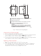
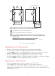
L1 (HOT) L2
1
1
3
2
4
4
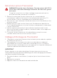
POWER SUPPLY. PROVIDE DISCONNECT MEANS AND OVERLOAD
PROTECTION AS REQUIRED.
BREAKS ON POSITIVE OFF.
EXPOSED UNUSED LEADWIRES TO BE PROPERLY INSULATED.
THERMALLY ACTIVATED—BREAKS ON TEMPERATURE
RISE. MAKES ON TEMPERATURE FALL.
L2
L1
L1
T2
T1
T1
CT410ACT410B
3
ELECTRIC
HEATER
CAUTION:
SPECIAL SERVICE CO/ALR SOLDERLESS CONNECTORS MUST
BE USED WHEN CONNECTING WITH ALUMINUM CONDUCTORS;
OTHERWISE, A FIRE HAZARD CAN RESULT.
TO
ELECTRIC
HEATER
M23412
1
2
3
4
Fig. 1 Thermostat wiring diagram.
Check Out Thermostat
1. Turn on the power to the heating system.
2. Turn setting knob all the way clockwise
; listen for clicking sound as
switch makes contact. Electric heater should begin operation.
3. Turn knob all the way counterclockwise
; listen for clicking sound as
switch breaks contact. Electric heater should shut off.
Setting Thermostat
1. Begin with setting knob at 70°F (20°C) on the scale.
2. If this setting is not satisfactory after at least two hours of operation,
turn setting knob up to raise the temperature, or down to lower the
temperature. Move knob only a degree each time.