
Submittal Sheet
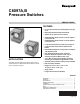
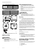
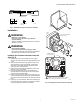
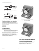
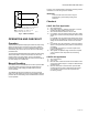
Table Of Contents

C6097A,B PRESSURE SWITCHES
5 65-0237—06
Fig. 3. 32003039-001 Position Indication Lamp Kit.
Installation
WARNING
Explosion or Fire Hazard.
Can cause severe personal injury, death or
property damage.
Observe all safety requirements each time a control is
installed on a burner.
WARNING
Electrical Shock Hazard.
Can cause serious personal injury or death.
Disconnect power supply before beginning installation.
More than one disconnection can be involved.
Installing the Position Indication Lamp Kit
(See Fig. 4)
1. Remove the cover from the C6097 by removing the
screws in the upper left and lower right quadrants of the
cover.
2. Place the lamp in the slot to the right of the dial, in the
upper right-hand corner of the C6097, with the base
down. Run the two lamp wires through the slit in the
upper left corner of the lamp slot.
3. Place the nut in the hexagonal depression in the lower
left-hand corner of the C6097.
4. Place the terminal plate over the nut and fasten the
terminal plate to the C6097 with the screw through the
bottom hole in the terminal plate.
5. Place the captive screw through the terminal lug on the
shorter wire and fasten the wire to the terminal plate with
the captive screw secured by the nut under the terminal
plate.
6. Using Fig. 5 or 6 for reference, fasten the terminal lug on
the longer lamp wire to either the normally open (NO) or
normally closed (NC) terminal of the C6097.
Fig. 4. Installing the Position Indicator Lamp Kit.
1-19/32 (40)
3-11/32 (85)
4-1/8 (105)
1/2
(13)
1/4 (6)
LAMP AND WIRES
TERMINAL
PLATE
CAPTIVE SCREW
AND NUT
SCREW
M16523
M16522
C6097
BODY
C6097
COVER
SLIDE TWO LAMP WIRES
THROUGH SLOT
LAMP
CONNECTIONS FOR
LAMP LEADWIRES
1
1
NC
NO
L2
CONNECT L1 (HOT) LEAD TO THE NO OR NC TERMINAL
BASED ON MODEL AND DESIRED LAMP FUNCTION.