
Submittal Sheet
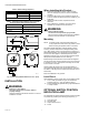
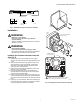
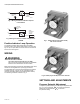
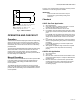
Table Of Contents

C6097A,B PRESSURE SWITCHES
65-0237—06 6
Fig. 5. Wiring the Position Indicator Lamp Kit
in the C6097A.
Fig. 6. Wiring the Position Indicator Lamp Kit in the
C6097B.
Position Indicator Lamp Operation
The Position Indicator Lamp will light when the C6097
Pressure Switch opens and provides power to the lamp (see
Fig. 5or 6). An option alarm circuit can also be connected as
shown in the same figures.
WIRING
WARNING
Electrical Shock Hazard.
Can cause serious personal injury or death.
Disconnect power supply before beginning installation.
More than one disconnection can be involved.
Make sure that all wiring agrees with all applicable local codes,
ordinances and regulations. An opening is provided to
accommodate rigid conduit or armored cable for line voltage
operation (see Fig. 3 and 4). Do not overload the switch
contacts (see Switch Ratings in the Specifications section).
The switching schematic is shown in Fig. 5.
Fig. 7. C6097 (manual reset switch model)
with cover removed.
Fig. 8. C6097 (recycle model) with cover removed.
SETTINGS AND ADJUSTMENTS
Pressure Setpoint Adjustment
To adjust the pressure setting, turn the setpoint adjustment dial
(Fig. 3, 4 and 5) clockwise to increase the pressure
setting and counterclockwise to decrease
the pressure setting.
C6097A
FLAME
SAFEGUARD
CONTROL
(RM78XX)
C
NO
NC
POSITION
INDICATION
LAMP
L1
L2
M16524
C6097B
FLAME
SAFEGUARD
CONTROL
(RM78XX)
C
NO
NC
POSITION
INDICATION
LAMP
L1
L2
M16525