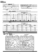
Honeywell C7015A Infrared Flame Detector The C7015A Flame Detector includes a lead sulfide photocell that is sensitive to the infrared radiation emitted by the combustion offuels such as natural gas, oil, and coal. n Particularily suitable for combination or dual-fuel applications. q When installed properly, can supervise the pilot flame and/or the main burner flame. w Mounts easily on a standard 314 inch sight pipe.
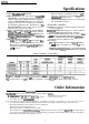
C7015A SPECIFICATIONS l ORDERING INFORMATION Specifications SUPER TWELINE MODELS l SUPER TRADELINE models offer features not available on TRADELINE or standard models, and are designed to replace a wide range of Honeywell and competitive controls. SUPER TRADELINE models are selected and packaged to provide ease of stocking, ease of handling, and maximum replacement value. Specifications of SUPER TRADELINE models are the same as those of standard models except as noted below.
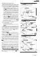
C7015A SPECIFICATIONS ACCESSORIES: 110634A Bushing with Focusing Lens 105134 Orifice Plate, to reduce the detector field of view. WIRING CONNECTIONS: Nominal 30, 48, or 96 in. [0.76, 1.22, or 2.44 ml leadwire+hvoNo. 18 AWG,flexible-tinnedconductom; rated for 194°F [90” C]; twistedpair-onebrown and one white. Leadwires enclosed in flexible metal cable-3/8 in. [9.6 mm] maximum outer diameter. DIMENSIONS: See Fig. 1. APPROVALS: Underwriters Laboratories Inc. listed: File No. MP268.
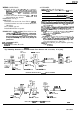
C7015A OPERATION l INSTALLATION Operation refractory radiation, thus making it fluctuate. This fluctuating action can simulate the flickering radiation from a flame, and infrared radiation may be present even after the refractory has visibly stopped glowing. Therefore, be very careful when applying an infrared detection system to be sure it responds only to flame. OPERATION OF INFRARED DETECTORS Infrared detectors can be used with gas, oil, coal, or dualfuel flames.
C7015A INSTALLATION is available to facilitate flame sighting after the C7015A is mounted. FIELD OF VIEW A lead sulfide photocell, like other photocells, views an area rather than a point. It is unable to pinpoint pilot flame locationaseasilyasaflamerod.Ifthedetectoristoproveonly the pilot jlame, it must view only a part of the flame so it can detect the pilot only when it is large enough to successfully light the main burner.
C7015A INSTALLATION INSTALLING AN ORIFICE PLATE AnorificeplatewithahexagonalorificediameterofO.125 in. [3.2 mm] is available for the C7915A Infrared Flame Detector. The orifice can be mounted in front of the cell in the seal-off adapter or in a standard 314 in. coupling. (Refer to Fig. 1.) The size of the sighted area at various distances can be determined from Table 4 or 5. For example, if the distance fromthephotocelltoa0.125 in. L3.175 mm] diameterorifice is4in. [101.
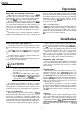
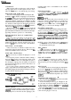
C7015A INSTALLATION RESPONSE TO HOT REFRACTORY Fig. 4--C7015A infrared Flame Detector aimed at side wall of combustion chamber. Although the infrared amplifier will not respond to steady radiation, as produced by hot refractory, be careful to protect the infrared detector from hot refractory radiation because of two possible conditions, shimmer and raa’iation saturation. a.
C7015A INSTALLATION mounting details, refer to form 60-0361 for the 118367A Swivel Mount) CLEARANCE Make sure there will be enough mom to easily mount the sight pipe, flame detector, and all required accessories, and to remove th flame e detecto for r troubleshooting and servicing. REDUCER BUSHING To mount the detector on a l/ 2 in. sight pipe, speci&zlly if replacing a FireyeW lead sulfuie detector, install a 390427 A Reducer Bushing (Fig. 1).
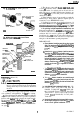
c701 !?A INSTALLATION 3. The detector comes with 30,48, or 96 in. [0.76,1.22, or 2.44 m] leadwires inside a flexible metal cable. The leadwires consist of a twisted pair-one brown and one white. The two no. 18 AWG flexible-tinned leadwires are rated for 194’ F [90” C]. The cable protects and electrically shields the leadwires. 4. If the leadwires are not long enough to reach the terminal strip or wiring subbase, make the required splices in a junction box (see IMPORTANT below). 5.
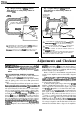
C7015A INSTALLATION l ADUSTMENTS AND CHECKOUT Fig. 1 l-Typical wiring of C7015A Infrared Flame Detector to distant wiring subbase or terminal strip. Fig. 1 O-Typical wiring of C7015A Infrared Flame Detector to nearby wiring subbase or terminal strip. FLEXIBLE CABLE (MECHANICALLY SUPPORT TO MINIMIZE MOVEh cmi5A FLEXIBLE CABLE (MECHANICALLY SUPPORT TO MINIMIZE MOVEMENT) GROUNDlNG STRAP, I RING SUBBASE OR TERh I BX CABLE, SHIELDED CABLE, OR TWISTED PAIR; MUST BE ALONE IN CONDUIT.
C7015A ADJUSTMENTS AND CHECKOUT and associated flame safeguard controls. Move the detector and sight pipe around to sight the flame at various positions and angles. Try to get a maximum steady meter reading. The signal must be above the minimum acceptable current/voltage listed in Table 6.
C7015A ADJUSTMENTS AND CHECKOUT PILOT TURNDOWN TEST Ifthedetectorisusedtoproveapilotflamebeforethemain fuel valve( can be opened, perform a Pilot Turndown Test before welding the sight pipe into position. Follow the procedures in the instructions for the appropriate flame safeguard control, and the burner manufacturer instructions. solids instead of liquids, or liquids instead of gases.
ADJUSTMENTS AND CHECKOUT FINAL CHECKOUT Before putting the burner into service, check out the installation by using the Checkout procedures in the instructions for the appropriate flame safeguard control. After completing the checkout, run the burner through at least one complete cycle to verify proper operation.
C7015A SERVICE n. PERIODIC MAINTENANCE 1. Clean the focusing lens andsightpipe when necessary. Remove the detector and use a soft, clean cloth. lhe lens does not require removal to clean it. If it is broken or damaged, or itiscoatedwithasubstancethatcannotbecleanedoff,replace the 110634A Bushing, which includes the focusing lens. 2. Keep the flame detection system adjusted for the smoothest, most reliable operation as recommended by the burner manufacturer. 3.
C7015A TABLE OF CONTENTS Table of Contents Application and Features 1.................................................................................................................................................. Page 1 Specifications ...................................................................................................................................................................... Ordering Information ...................................................................................