
notherm IV T8611G Instruction Manual

69-0936—1
2
T8611G CHRONOTHERM
®
IV DELUXE PROGRAMMABLE HEAT PUMP THERMOSTATS
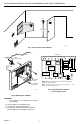
W2
L1
(HOT)
L2
M11311
FAN
RELAY
Y1 G E
THERMOSTAT
C
HEAT
RELAY
1
RW1
COMPRESSOR
CONTACTOR
EM. HT.
RELAY
TRANSFORMER
HEAT
RELAY
2
OT OT
OUTDOOR
SENSOR
COOLING OR
HEATING
CHANGEOVER
VALVE
O/B
X2 LX1
EQUIPMENT
MONITOR 2
EQUIPMENT
MONITOR 1
1
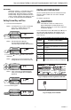
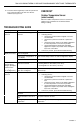
POWER SUPPLY. PROVIDE DISCONNECT MEANS AND OVERLOAD
PROTECTION AS REQUIRED.
EM. HT. RELAY DOES NOT CYCLE. TO TURN OFF THE EM. HT.,
SET SYSTEM SELECTION TO HEAT.
2
1
2
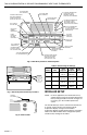
WIRES
THROUGH WALL
WALL
MOUNTING
HOLES
M15044
MOUNTING
SCREWS
WALL
ANCHORS
(2)
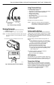
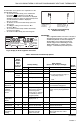
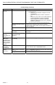
Fig. 1. Typical location of thermostat.
Fig. 3. Typical hookup of T8611G
in a heat pump system.
5 FEET
[1.5 METERS]
YES
NO
NO
NO
M10106
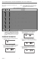
Fig. 2. Mounting the wallplate.
IMPORTANT
Use 18 gauge, color-coded thermostat cable for
proper wiring.
2. Securely tighten each terminal screw.
3. Push excess wire back into the hole.
4. Plug the hole with nonflammable insulation to
prevent drafts from affecting the thermostat.