
Submittal Sheet
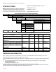
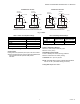
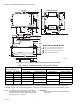
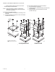
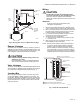
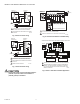
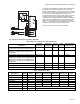
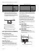
Table Of Contents

SERIES 61 AND SERIES 62 MODUTROL IV™ MOTORS
63-2629—06 10
Table 8. Resistor Table 1 Table 9. Resistor Table 2
NOTE: Vibration does not affect Modutrol IV Motor
performance (as it did in earlier Modutrol Motors).
When replacing a motor that was connected to an
R927C or R9107A Relay, Honeywell recommends
performing a retrofit to remove the relay and the old
motor. Replace both with one Series 90 Modutrol IV
motor (that is, do not replace the relay).
.
Fig. 11. Auxiliary switch schematic.
SETTINGS AND ADJUSTMENTS
Before Setting Stroke
1. Remove the top cover from the motor.
2. Disconnect the controller from the motor.
3. For models with an internal transformer (line voltage
motors), ensure that power (and nothing else) remains
connected to the motor.
IMPORTANT
Detach linkage from motor before adjusting stroke.
Adjustable Stroke
Series 61 Adjustable Stroke
When viewing from the power end of the motor, the stroke
potentiometer is to the far left. To set the stroke to 160°
(maximum position) turn the potentiometer fully clockwise
, using a 1/8 in. straight-blade screwdriver. To set the
stroke at 90° (minimum position) turn the potentiometer fully
counter-clockwise . Setting the potentiometer anywhere
between fully clockwise and fully counter-clockwise will set the
stroke between 160° and 90°.
Series 62 Adjustable Stroke
When viewing from the power end of the motor, the stroke
potentiometer is to the far left. The sensitivity potentiometer is
to the far right. To set the stroke to 160° (maximum position)
turn both potentiometers fully clockwise , using a 1/8
inch straight-blade screwdriver. To set the stroke at 90°
(minimum position) turn both potentiometers fully counter-
clockwise . Setting the potentiometer anywhere between
fully clockwise and fully counter-clockwise will set the stroke
between 160° and 90°.
CAUTION
Careless Installation Hazard.
Use of excessive force while adjusting cams
damages the motor.
To avoid damaging motor end switches, set cams by
moving only the screwdriver top.
CAUTION
Equipment Damage Hazard.
Can damage the motor beyond repair.
Never turn the motor shaft by hand or with a wrench.
Forcibly turning the motor shaft damages the gear train
and stroke limit contacts.
Fig. 12. Stroke adjustments setup.
Number of Slaves in Parallel Resistor Value
1NONE
2 3500 Ohms
3 2000 Ohms
4 1300 Ohms
5 1000 Ohms
6 800 Ohms
Number of Slaves in Parallel Resistor Value
1NONE
2 5000 Ohms
3 2400 Ohms
4 1700 Ohms
5 1400 Ohms
6 1200 Ohms
BLUE LEAD
YELLOW LEAD
RED LEAD
USE NEC CLASS 1 WIRING UNLESS POWER SUPPLY
MEETS CLASS 2 REQUIREMENTS. TAPE UNUSED LEADS.
ENSURE THE CURRENT DRAW OF THE EXTERNAL CIRCUIT
IS LESS THAN SWITCH CONTACT RATING.
ON TWO-SWITCH MOTORS, SECOND SWITCH HAS BLACK
LEADS WITH BLUE, YELLOW, AND RED TRACERS.
SOME AUXILIARY SWITCH ASSEMBLIES INCLUDE ONLY
RED AND YELLOW LEADS. SOME OTHERS DO NOT INCLUDE
THE YELLOW LEAD.
M17099
1
1
1
2
2
2
2
3
3
M13601
POWER END
OF MOTOR
AUXILIARY
SWITCH CAMS
SENSITIVITY
POTENTIOMETER
(ON SOME SERIES 62
MODELS, SEE TABLE 5)
ADJUSTABLE
STROKE
POTENTIOMETER