Technical Overview For Mark III Communications Management Unit (CMU) 23 July 2002 HONEYWELL Aerospace Electronic Systems Use or disclosure of information on this page is subject to the restrictions on the title page of this document.
HONEYWELL Aerospace Electronic Systems Use or disclosure of information on this page is subject to the restrictions on the title page of this document.
1 INTRODUCTION 1.1 Mark III CMU Overview Honeywell provides a family of Datalink products, ranging from the AFIS product for the business Jet market, to our Mark II and Mark III CMUs for the Air transport and Military market. The Mark III Communications Management Unit (CMU), discussed in this document, is Honeywell’s High-End “Next Generation” CMU.
• Define uplink and downlink message formats • Define the format of printed messages • Specify trigger logic (i.e.
time and money. However, to deliver the future datalink capability required by the airlines, both ground and airborne systems must have a transition to the next generation architecture. The Mark III CMU offers a datalink user the next generation ARINC 758 CMU capable of providing the datalink functionality to meet the industry demands for today and tomorrow. 1.
includes such services as Providing world-wide Weather messages to the aircraft, as well as being an FAA approved distributor of messages such as Pre-Departure Clearances and ATIS. The Honeywell Aircraft Maintenance and Operational Support System (AMOSS) provides ground ACARS message processing and integration with flight planning systems. Finally, Honeywell provides world class product support worldwide.
2 SYSTEM OVERVIEW 2.1 Hardware Overview The Mark III CMU is based upon the Multiple Application Processing System (MAPS) platform which is the new generation hardware that will be used for introduction of new Honeywell datalink products. This common hardware platform will facilitate the introduction of communication products that integrate new capabilities with the Mark III CMU. The Mark III CMU is a single Line Replaceable Unit (LRU) housed in a standard 4 MCU ARINC 600 form factor.
Figure 1 Mark III CMU Front Panel ARINC 607 defines the Aircraft Personality Module (APM) which contains all aircraft and system configuration information. The APM is external to the MARK III CMU and is a permanent fixture in the aircraft. Only one APM is required per MARK III CMU installation (one APM for each MARK III CMU mounting tray). The same APM part number is used on all aircraft in the fleet. 2.2 System Interfaces The Mark III CMU supports an extensive set of interfaces.
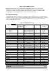
Portable Data Loader 615 High speed ARINC 429 1 Baseline Ethernet Data Loader 615A Ethernet 10BaseT note 2 Growth PCMCIA --PCMCIA 1 Baseline Notes: 1. Supports up to 2 total SDUs, whether ARINC 741 or 761. 2. The Mark III provides 4 10BaseT Ethernet ports which can be used for any purpose. 3. Supports 1 ARINC 740/744 printer in baseline. An additional printer can be added to one of the spare ARINC 429 ports. This requires a software upgrade. 4. Supports 3 FMCs in the AT & Mil products. 5.
Satellite Communications (SATCOM) The Mark III CMU can be configured to interface with one or two ARINC 741 compliant Satellite Data Units (SDUs) via low speed ARINC 429, or can be configured for high speed 429. The industry is still working on the definition of the ARINC 761 specification for second generation satellite communications systems, which will include access to Low Earth Orbit (LEO) and Medium Earth Orbit (MEO) satellite constellations.
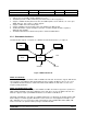
Control and Display Unit (CDU) In the business jet and regional aircraft market place, there is limited cockpit pedestal real estate. Often, these aircraft are equipped with a 4-line-select key CDU instead of a 6-line-select key MCDU. The Mark III CMU can be configured to interface with one or two of these CDU devices via an RS-422 interface. MCDU MCDU MIDU CDU Figure 2.2.
2.2.3 LRU Interfaces In general, the Mark III CMU can support any LRU that uses the ARINC 429 File Data Transfer Protocol or Williamsburg Protocol to communicate as an end system, as defined in ARINC 619 (ACARS file transfer protocols for other devices).
an extensive amount of ARINC 429 broadcast data providing aircraft performance related data. All of the ARINC 429 broadcast data is available via the FIDB to be used by both the HGI and the AMI. Cabin Terminal The Mark III CMU can be configured to support up to two Cabin Terminals operating as end systems.
future to define Warm and Hot spare requirements. This effort has not yet started. As the Mark III CMU hardware was designed to support Dual capability, Updated dual capability could be provided with a software upgrade. Ethernet ARINC 646 defines an Ethernet Local Area Network (ELAN) aboard an aircraft. The Mark III CMU provides four 10BaseT Ethernet ports that can be used for various applications which could include Gatelink connectivity, ARINC 615A data loading, ARINC 744A printer and ELAN connectivity.
through an automated code generation system specific to the target environment. Automated test scripts are also derived from the model database. (See Figure 6). The software architecture was developed to isolate target-specific components from the core software components.
CMU AOC HGI AMI FIDB GBST Figure 7 Database Design The Flexible Input Data Base (FIDB) contains a list of all I/O parameters available for all aircraft within a fleet. The FIDB contains information regarding LRU source, data busses, labels, scaling, and resolution for each I/O parameter. The Airline Modifiable Information (AMI) database is generated by the user to customize their AOC application. AOC screen and print formats, message definitions and trigger logic can all be specified in the AMI.
2.4 Certification Honeywell received the 1st FAA certification in December 2001. This initial certification was for Embraer aircraft. The Mark III CMU has since also been type certified by Boeing. Contact Honeywell for up-to-date information on other certifications completed or in work. HONEYWELL Aerospace Electronic Systems Page 17 Use or disclosure of information on this page is subject to the restrictions on the title page of this document.
3 FUNCTIONAL OVERVIEW The Mark III CMU is designed to provide complete datalink capability, providing interfaces and support to today’s installed equipment. In addition, Honeywell as well as the industry recognizes that Datalink features will be expanded over time, and is in fact the principle behind the current ARINC 758 characteristic. A Characteristic that was developed to define current operation (referred to as Level O.1A), and allow expansion over time to support new requirements and needs.
A758 Level A Application Functions Airline/AOC Applications and ATS Messages ACARS End System ARINC 620: AOC ARINC 620: AAC ARINC 623: ATIS ARINC 623: PDC ARINC 623: Oceanic Clearance B +ATS Applications Support and Flight Deck I/F Compatible w/ Non-Radar ARINC 622: ACARS Convergence Function (ACF) ARINC 622: Air Traffic Facilities Notification (AFN) ARINC 745: Automatic Dependent Surveillance - Advanced (ADS-A) C RTCA/DO219: Controller/Pilot Data Link Communications (CPDLC)/ATS Datalink (ATS DL) + ATN
Once an AOC message has been viewed by the flight crew (and any required user action has been taken), it can be placed in one of 8 user defined review categories. ATC messages have a separate review category. The flight crew can access messages placed in the review categories at any time. A useful analogy for ACARS message processing is an email system. When a new email arrives, the user is alerted ("you have mail") and the message goes into an inbox.
Once the downlink message has been sent, the message will be placed in the user defined review category specified for the message. System Pages The Mark III CMU provides a series of pages that allow users to perform various communications system functions. These system pages allow the flight crew to switch the VHF radios between voice and data and between 8.33 Khz and 25 Khz as well as manually selecting a frequency.
• • • • Maintenance Memory Integrity: Verify that faults that are written to the maintenance memory are correctly retained in memory. Over-temperature Monitor: Monitor internal LRU temperature and log a fault if normal operational temperature limits are exceeded. Interface Tests: Verify physical connections, wiring, and input and output circuitry. Network Subsystem Test: Verify availability and status of equipment on networks and busses.
3 D8PSK TDMS 4 GMSK STDMA kbps. Same as Mode 2 except the voice is now digitized and the Medium Access changes. Currently. Discussions are underway to determine if Mode 3 will be deployed. This is currently only a U.S. program, with earliest use for datalink scheduled for 2011 (but potentially 4 years earlier for voice) Modulation and Medium Access change and output is only 19.2 kbps. Mode 4 is being considered as one of the means to perform ADS-B communication.
support as part of the baseline the text Weather uplinks which has become standard use within the Air transport industry. ATN The industry has embarked on the definition of a new communications standard named the Aeronautical Telecommunications Network (ATN). The ATN offers a standardized, robust, and efficient communications mechanism that provides additional services. Honeywell has been a leading member of the international consortium, Aeronautical Communication Inc.
the addition of encryption algorithms in the future. As part of this work, Honeywell is currently under contract with the U.S. government to define long term concepts for encryption and authentication associated with use in ATN and non-ATN environments. HONEYWELL Aerospace Electronic Systems Page 25 Use or disclosure of information on this page is subject to the restrictions on the title page of this document.
4 DATABASES Honeywell pioneered the concept of airline reconfiguration and partitioned software for datalink systems in the early 1990s. The reconfiguration concept has continually evolved and improved as each new product has been introduced. Reconfiguration started in the industry with the Honeywell Mark II ACARS unit, and expanded with the B-777 and Mark II CMU.
Mini-FIDBs Master FIDB 737-300 Customer FIDB (same for all a/c in fleet) 737-400 AMI/HGI (same for all a/c in fleet) 737-500 • • • • • • A319 • • • Aircraft Type: ERJ-145 • • • APM ERJ-145 • • • • • • Customer Aircraft Types: 737-400 737-500 A319 ERJ-145 GEX (specific to a/c type & configuration) Figure 10 FIDB Architecture The FIDB defines the same name for a given aircraft parameter (i.e., Air_Speed) regardless of aircraft type.
AMI FIDB HGI FIDB Mark III CMU Customer Honeywell Figure 11 AMI/HGI Generation The GST offers a robust set of capabilities that allow the user to completely customize their AOC application.
4.2.1 Menus Since the AOC application is completely customizable, the user can define the set of menus that navigate through the various AOC datalink pages. Using the GBST Display Editor, the user types in the text for the menu items, selects the prompt symbol and uses the mouse to move the text next to the line select key to be used to select the menu item. Figure 12 is an example of a main menu screen defined using the GBST Display Editor.
Screens, including menus, can consist of multiple (up to 9) pages. Note the 1/2 in the upper right corner of the Main Menu display indicating page 1 of 2. Pages are accessed by using the Next and Previous page buttons on the display unit. Figure 13 shows page 2 of the example Main Menu. Figure 13 Main Menu Page 2 HONEYWELL Aerospace Electronic Systems Page 30 Use or disclosure of information on this page is subject to the restrictions on the title page of this document.
The GBST supports the screen layouts for both the standard ARINC 739 14 line MCDU/MIDU as well as supporting Honeywell’s 9 line CDU (used on various aircraft types such as the Embraer 135/145, and others). Figure 14 shows an example Main Menu on a 9 line CDU. Figure 14 CDU Main Menu (Supporting Regional / Business Jet CDUs) HONEYWELL Aerospace Electronic Systems Page 31 Use or disclosure of information on this page is subject to the restrictions on the title page of this document.
This discussion of the GBST and how it is used is equally applicable to both the AMI and the HGI. However, the HGI is only modifiable by Honeywell as it contains controlled data that requires re-certification upon change. There is a baseline HGI for both the 14 line MCDU/MIDU and the 9 line CDU. Therefore, the set of ATS menus and screens will be pre-defined and the user will only need to ensure that there is an ATS prompt on one of the menus (typically the Main Menu) that invokes the ATS menu.
In addition to the AOC screens defined by the AMI, and ATC screens defined by the HGI, there are additional menus screens within the Mark III CMU, referred to as System screens. The System pages provide the capability to perform various communications management and maintenance functions. These pages are part of the Mark III embedded operational software (not part of the reconfigurable AOC screens). When defining the AMI, the user would also tie in the System pages from one of the menu prompts.
4.2.2 Uplinks For uplink messages, the user can define both the screen layout and the uplink message format. Figure 17 depicts an example screen layout for a Clearance Uplink. As part of the display definition, the user specifies the properties of the message display including which review categories this message type should be placed into after initial viewing.
When defining the format and characteristics of an uplink message (i.e., the decoding), the user can specify the elements within the message (see Figure 18), the properties of the message including whether to generate a scratchpad alert and the message references (see Figure 19).
Figure 19 Clearance Message References If a crew response is required, the user would typically create response action prompts, such as the ACCEPT and REJECT prompts shown in Figure 17. Selection of these prompts by the flight crew will send a message to the ground indicating acceptance or rejection of the Clearance message. The action prompts at the bottom of the screen are shown in yellow indicating that they are part of a common footer.
The user can also specify a REJECT REASONS action prompt, which allows the flight crew to specify the reason for rejecting the Clearance (see Figure 20). Figure 20 Reject Reasons HONEYWELL Aerospace Electronic Systems Page 37 Use or disclosure of information on this page is subject to the restrictions on the title page of this document.
There are a number of different types of objects that can be placed on a display. As an example, for the Main Menu, page prompts are used to link to other pages. The Main Menu also used a constant text string for the title. The Clearance Uplink display had RETURN and PRINT prompts as well as the ACCEPT, REJECT, and RESP REASONS action prompts. Real-time parameters (such as from the FMS, or internally computed within the CMU, or received from other subsystems) can be displayed on screens.
4.2.3 Downlinks The definition of the AOC downlinks is created using the GBST. The definition of downlink message screens and associated message formats (encodings) is the same as for uplinks. Figure 22 is an example of a Diversion Report Downlink screen format. Figure 22 Diversion Report Downlink Within the properties of the downlink message display, the user can specify the review category the message will be placed into.
Like the Reject Reasons page, the Diversion Report Downlink display contains a scrolling prompt and a conditional display field that is only displayed upon a certain value of the scroll field. Figure 23 shows the Diversion Reasons values. The text field below the diversion reason is only available when the diversion reason is "other". Figure 23 Diversion Reasons Two other object types that can be used on a display are toggle prompts and exclusive selector prompts (ESPs).
Figure 24 Divert Message Elements Figure 25 Divert Properties HONEYWELL Aerospace Electronic Systems Page 41 Use or disclosure of information on this page is subject to the restrictions on the title page of this document.
4.2.4 Print Definition The user can define the print format for a message by specifying the field names and associated parameters. Figure 26 shows the print format for a Flight Initialization uplink. This allows the user to define formats for uplink messages, as well as Mark III CMU generated reports to be easily readable by the flight crew. It also allows the flexibility to modify such formats as user requirements change. Figure 26 Print Format 4.2.
Logic units can be used to specify OOOI conditions. OOOI logic can be as simple or as complex as the user requires. Figure 27 depicts a portion of an example logic unit for OOOI events. Figure 27 OOOI Logic Unit 4.2.6 Preferred Channel Management Honeywell first introduced the concept to the industry of automated frequency management based on aircraft position. This is in contrast to the brute force approach of performing frequency management by trial and error based on a table of possible frequencies.
to use for message transmission. The user also can specify the set of VHF frequencies to use for that region. Figure 28 shows an example. Figure 28 Regions In this example, 5 regions are defined: Europe, US, Canada, Mexico, and Cuba. The OTHER region is used for all portions of the world not covered by the other user-defined regions. The DEFAULT region is used for the entire world when the aircraft position data is unavailable.
Figure 29 US Map HONEYWELL Aerospace Electronic Systems Page 45 Use or disclosure of information on this page is subject to the restrictions on the title page of this document.
Figure 30 Areas The Mark III CMU GBST provides the next generation in Airline reconfiguration. It is specifically designed to provide airlines with the freedom and flexibility to customize the AOC functions in the CMU, and to allow users to expand the Mark III CMU as their requirements change. As part of the GBST, there is an extensive configuration control application built into the GBST, which allows airlines to manage the changes to the AMI database using the GBST.
5 HARDWARE DESCRIPTION 5.1 Mechanical Design The MARK III is a modular design that consists of a number of circuit card assemblies (CCAs) which are enclosed in a lightweight aluminum chassis. The internal interconnect between circuit card assemblies consists of a combination of highly reliable card-to-card connections and aerospace quality ribbon cables. The rear interconnect circuit card assembly provides most of the connections between CCAs.
5.1.2 Processor CCA The processor circuit card assembly contains the MARK III core microprocessor, supporting logic circuits, and memory devices.
• • • Patented multi-layer microstrip/fiberglass high reliability printed wiring board (PWB Analog Output Discretes PCI BUS-based Connector 5.1.5 Spare CCAs (Growth) The MARK III provides two CCA growth slots for expansion. The growth slots may be used to provide an integrated VHF Data Radio (VDR) into the MARK III, memory expansion to allow the CMU to act as an aircraft file server, or other product variants. Minimum features of the Spare CCAs are: • • PCI BUS-based Connector. BITE Circuitry. 5.
MCDU 1 PRNTR 1 CMC FMC 1 General Data Cabin 1 Cabin 2 Spar e Spar e General Data ADL Spar e Spar e Spar e General Data VDR 3 XPDR 2 SDU 2 Gatelin k Comm Link Data DCDU 1 702A 1 Spar e Flight System Data CMU.
APM Interface APM SDI PGM VHF PGM Local Program Pins Data Loader Disc Dataloade r Doors/Brakes/e tc OOOI Sensors Alert Contacts #1 & #2 Crew Alerts Ethernet #1 Ethernet #2 Ethernet #3 Ethernet #4 Tip/Ring UHF Radio CD810/815 RS-422 VHF Control VHF (Operating in 716 Mode) VOICE/DATA MON VOICE/DATA SEL Data Key Port Select VOICE/DATA Mode MSK Audio PCMCIA Size II Card 1553B #1 CMU Reserved Discretes User Defined I/O RS-422 CD810/815 Performance Computer PZ800 PC (DMT) PCMCIA RS-422 PC (DLT)
5.3 Mechanical Packaging 5.3.1 Unit Weight The MARK III LRU maximum weight is twelve pounds. 5.3.2 Unit Size The MARK III LRU is a 4-MCU box that meets the dimensional specifications in ARINC 600. The unit has the following dimensions in inches: MARK III Width* Height* Length (Maximum) Length+Front Face Projections (Maximum) 4.88 + .020 7.62 + .020 12.76 15.26 * Height and Width are for Unit Cover, the Front plate shall slightly exceed these dimensions. 5.3.
5.4 Environmental Specifications The following DO-160D categories will be used for the MARK III: Temperature and Altitude (DO-160D Section 4.
Waterproofness (DO-160D Section 10.0) Category X, Not Applicable Fluids Susceptibility (DO-160D Section 11.0) Category X, Not Applicable Sand and Dust (DO-160D Section 12.0) Category X, Not Applicable Fungus Resistance (DO-160D Section 13.0) Category X, Not Applicable Salt Spray (DO-160D Section 14.0) Category X, Not Applicable Magnetic Effect (DO-160D Section 15.0) Category Z, Less than 0.3m for 1 degree deflection Power Input (DO-160D Section 16.
Category A2, Pin Injection Tests (DO-160C Section 22.5.1) Waveform 3 (DO-160D Section 22, Figure 22-4), Voc/Isc = 250V/10A, and Frequency = 1 Mhz + 20%. Waveform 4 (DO-160D Section 22, Figure 22-5), Voc/Isc = 125V/25A. Category E3, Cable Bundle Tests, Cable Induction (DO-160C Section 22.5.2) Waveform 1 (DO-160D Section 22, Figure 22-2), Vl/It = 300V/600A. Waveform 3 (DO-160D Section 22, Figure 22-4), Vt/Il = 600V/120A, and Frequency = 1 Mhz and 10 Mhz Lightning Direct Effects (DO-160D Section 23.
Nominal Minimum Maximum +27.5 Vdc +20.5 Vdc +32.2 Vdc Nominal Maximum 50 Watts 100 Watts 5.5.3 28 Vdc Backup Input Power Requirements The MARK III does not require use of standby 28 Vdc Battery Backup Input Power. 5.5.4 Power Interrupt Requirements The MARK III shall be capable of continuous operation through any power-off transient under 200 milliseconds. Non-volatile data shall be unaffected by Input Power Loss and does not depend upon a standby 28 Vdc Battery Bus, if the aircraft is so equipped.
6 SUMMARY The Mark III CMU is a high-end system which provides the latest in both hardware and software technology, unequalled in the industry. In addition to the Mark III CMU, Honeywell also manufactures a Mark II CMU, which is provided for both 724B wiring or 758 wiring, as well as other datalink related products including cockpit printers, Multi-Input Interactive Display Units (MIDUs); and VHF, HF and SATCOM systems. The following provides a summary of the Mark III CMU.
The Mark III CMU has also been designed to support a future upgrade for new Gatelink technology. With the advent of commercialized 2.4 GHz spread spectrum wireless communication, a new technology is emerging for the airline industry for providing the ability to transmit very large data packets from and to the aircraft when in the vicinity of a short range transceiver (commonly referred to as Gatelink).
The Mark III CMU is designed to provide airlines with a hardware platform with the best growth potential of any system in the market. Not only does it contain significantly more processing power than other systems; it is also designed to support such future capabilities as Gatelink. The software within the Mark III CMU is also designed to provide customers with more control over AOC functional changes.