
Submittal Sheet
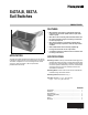
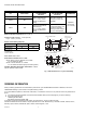
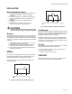
Table Of Contents

S437A,B, S637A SAIL SWITCHES
3 60-2186—2
INSTALLATION
When Installing this Product...
1. Read these instructions carefully. Failure to follow them
could damage the product or cause a hazardous
condition.
2. Check the ratings given in the instructions and on the
product to make sure the product is suitable for your
application.
3. Installer must be a trained, experienced service
technician.
4. After installation is complete, check out product
operation as provided in these instructions.
CAUTION
Disconnect power supply before connecting wiring
to prevent electrical shock and equipment damage.
Mounting
Plan the location so that the sail will be in the direct path of an
unrestricted air stream. A horizontal duct run is best because
the sail will then move horizontally. In a vertical duct, the effect
of gravity on the linkage changes the operating characteristics
somewhat.
1. At the desired location, cut a rectangle hole 1-1/2 x 2 in.
See dotted lines in dimension drawing.
2. Note direction of air stream and position chassis as a
template to make the two mounting hole locations.
3. Center punch and drill mounting holes. Secure device
with sheet metal screws.
WIRING
Disconnect power supply before making wiring connections to
avoid possible electrical shock or equipment damage. All
wiring must agree with local codes and ordinances.
Wire the sail switch in series with the load to act as an air
velocity limit switch.
Fig. 2. S437 Schematic and Typical Connections
Fig. 3. S637 Schematic and Typical Connections.
Set Differential
The knurled wheel at the base of the switch is marked with the
letters A, B, C, D to indicate relative differentials from minimum
to maximum. Follow instructions of system manufacturer, if
available, or adjust to suit actual operation.
A minimum differential setting (position A) of approximately
550 fpm (2.8 m/s) results in a make velocity of approximately
1900 fpm (9.7 m/s). The break velocity is 1350 fpm (6.9 m/s)
for any setting of the differential.
Sail Size
All velocities given above are for a standard size sail. The large
sail operates the switch at reduced velocities.
To control at higher velocities, the size of the sail must be
reduced in inverse proportion.
Example: 2 x velocity = 1/2 sail size.
CHECKOUT
Operate the system through at least one complete cycle to
make certain all equipment is controlled properly.
1 SWITCH MAKES ON INCREASING AIR VELOCITY.
1
M27087
TO
LOAD
S437A, B
NC NC
C
TO
SIGNAL
COMMON
TO
LOAD
S637A
1 SWITCH MAKES C TO NO ON INCREASING AIR VELOCITY.
M27088