
Use and Care Manual

English: Page 1 • Français : Page 6 • Español: Página 11
3 69-1958EFS—02
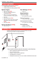
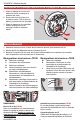
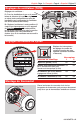
1. Pull wires through wire
hole. Position wallplate on
wall, level, and mark hole
positions.
2. Drillholes(3/16”fordrywall,
7/32”forplaster)andtapin
supplied wall anchors.
3. Pullwirethroughwallplate,
position over anchors, then
insert and tighten mounting
screws.Checklevelif
desired.
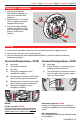
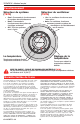
1. Loosenscrewterminals,insertwiresintoterminalblock,thenre-tightenscrews.
2. Pushexcesswirebackintothewallopening.
3. Plugthewallopeningwithnonflammableinsulationtopreventdraftsfromaffecting
thermostat operation.
Wiring
NOTES
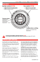
R & Rc terminals (T87N)
Insingle-transformersystem,leavemetal
jumperinplacebetweenR&Rc. Remove
metaljumperiftwo-transformersystem.
Heat pump systems (T87N)
Ifwiringtoaheatpump,useasmallpiece
ofwire(notsupplied)toconnectterminalsW
and Y.
Wire specifications
Use18-gaugethermostatwire.Shieldedcable
is not required.
Wallplate installation
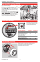
Terminal Designations—T87N
W Heat relay.
Y Compressor contactor.
G Fanrelay.
O Heat pump changeover valve
energized in cooling.
Rc Cooling power. Connect to secondary
sideofcoolingsystemtransformer.
R Heating power. Connect to secondary
sideofheatingsystemtransformer.
B Heat pump changeover valve
energized in heating.
Terminal Designations—T87K
W Heat relay.
R Power.Connecttosecondarysideof
heatingsystemtransformer.
Y Thisterminalcanbeusedforsome3-
wirehot-watervalvesystems(power
openandclosevalves).
R
W
Y