
Product manual


Monitoring and Operating the Controller
4/07 UDC2500 Universal Digital Controller Product Manual 99
4.7 Start Up Procedure for Operation
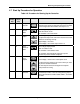
Table 4-6 Procedure for Starting Up the Controller
Single
Display
Step
Dual
Display
Step
Operation Press Result
1 1 Configure
controller
SetupSetup
Make sure the controller has been configured properly
and that all the values and selections have been recorded
on the Configuration Record Sheet. See steps 4 & 5.
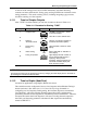
2 Select
Manual
Mode
M-A
Reset
M-A
Reset
M-A
Reset
N/A for Single Display Model
Until “M” indicator is ON.
The controller is in manual mode.
3 Adjust the
Output
or
N/A for Single Display Model
To adjust the output value and ensure that the final control
element is functioning correctly.
Upper Display = PV Value
Lower Display = OT and the output value in %
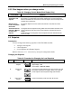
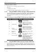
4 Select
Automatic
Mode
M-A
Reset
M-A
Reset
M-A
Reset
N/A for Single Display Model
Until “A” indicator is ON.
The controller is in Automatic mode.
The controller will automatically adjust the output to
maintain the process variable at setpoint.
2 5 Enter the
Local
Setpoint
Lower
Display
Lower
Display
Lower
Display
Upper Display = Pv Value
Lower Display = SP and the Local Setpoint Value
or
To adjust the local setpoint to the value at which you want
the process variable maintained.
The local setpoint cannot be changed if the Setpoint
Ramp function is running.
3 6 Tune the
Controller
SetupSetup
Use Accutune to tune the controller; see product manual
for detailed procedure or refer to Tuning Set Up group to
set that the selections for PB or GAIN, RATE T, and I MIN
or I RPM.