
Product manual

Monitoring and Operating the Controller
4/07 UDC2500 Universal Digital Controller Product Manual 131
4.23 Configuring your Ethernet Connection
Introduction
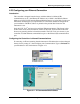
This controller is shipped from the factory with the address for Infrared (IR)
communications set to 3, the Ethernet IP Address set to 10.0.0.2, the Ethernet Subnet
Mask set to 255.255.255.0 and the Ethernet Default Gateway set to 0.0.0.0. Consult your
Information Technologies (IT) representative as to how these should be configured for
your installation. The MAC address is printed on the product label located on the
instrument’s case.
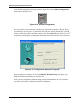
Only the P.I.E. Tool
®
can be used to configure Ethernet parameters. The figures in this
section show screen-shots from the PC version of the P.I.E. Tool
®
Screens. Pocket PC
Screens are generally similar in format but smaller. The P.I.E. Tool can connect to your
controller via either Ethernet communications port or the Infrared (IR) communications
port.
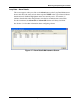
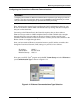
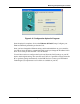
Configuring the Controller via Infrared Communications
If connecting via IR and assuming that the instrument’s IR address has not been changed
from its factory setting of 3, then configure your Communications Type as Infrared and
your IR address to 3 as shown below in Figure 4-11.
Figure 4-11 IR Communications Address