
Product manual

Input Calibration
4/07 UDC2500 Universal Digital Controller Product Manual 139
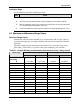
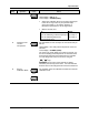
Table 5-2 Voltage and Milliamp Equivalents for Input 2 Range Values
Range Values Sensor Type PV Input Range
0 % 100 %
Linear
Milliamps
4 to 20 mA
0 to 20 mA
4.00 mA
0.00 mA
20.00 mA
20.00 mA
Volts
1 to 5 Volts
0 to 5 Volts
0 to 2 Volts
1.00 Volts
0.00 Volts
0.00 Volts
5.00 Volts
5.00 Volts
2.00 Volts
5.3 Preliminary Information
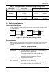
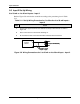
Disconnect the Field Wiring
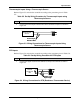
Tag and disconnect any field wiring connected to the input (#1 or #2) terminals on the
rear of the controller.
XXXX
R
+
_
Input 1
Connections
25 R
26 +
27 –
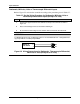
mA+
Volt+
Input 2
Connections
22 mA+
23 V+
24 –
_
Input 1
Input 2
Figure 5-1 Input 1 and Input 2 Wiring Terminals
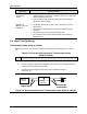
Equipment Needed
Table 5-3 lists the equipment you will need to calibrate the specific types of inputs that
are listed in the table. You will need a screwdriver to connect these devices to your
controller.
Table 5-3 Equipment Needed
Type of Input Equipment Needed
Thermocouple
Inputs (Ice Bath)
• A calibrating device with at least ± 0.02 % accuracy for use as a
signal source such as a millivolt source.
• Thermocouple extension wire that corresponds with the type of
thermocouple that will be used with the controller input.
• Two insulated copper leads for connecting the thermocouple
extension wire from the ice baths to the mV source.
• Two containers of crushed ice.
Thermocouple
Inputs (T/C Source)
• A calibrating device with at least ± 0.02 % accuracy for use as a
signal source such as a millivolt source.
• Thermocouple extension wire that corresponds with the type of
thermocouple that will be used with controller input.