HP Hub & Switch Management for OV-UX User Guide
© Copyright 1998 Hewlett-Packard Company All Rights Reserved. This document contains information which is protected by copyright. Reproduction, adaptation, or translation without prior permission is prohibited, except as allowed under the copyright laws. Publication Number Edition 1 September 1998 Applicable Product Disclaimer The information contained in this document is subject to change without notice.
Contents 1 Information About HP Hub & Switch Management for OV UX Introduction . . . . . . . . . . . . . . . . . . . . . . . . . . . . . . . . . . . . . . . . . . . . . . . . . . 1-1 Features of HP Hub & Switch Management . . . . . . . . . . . . . . . . . . . . . 1-2 HP Proactive Networking . . . . . . . . . . . . . . . . . . . . . . . . . . . . . . . . . . . . . 1-2 Support for New Switches . . . . . . . . . . . . . . . . . . . . . . . . . . . . . . . . . . . . 1-3 Technical Product Support . . . . . . .
Starting HP OpenView . . . . . . . . . . . . . . . . . . . . . . . . . . . . . . . . . . . . . . . 4-1 Verifying Installation of the Manager Product Set . . . . . . . . . . . . . . 4-3 Stopping and Restarting the Manager Application . . . . . . . . . . . . . . . 4-4 Stopping the Manager . . . . . . . . . . . . . . . . . . . . . . . . . . . . . . . . . . . . . . . . 4-4 Restarting the Manager . . . . . . . . . . . . . . . . . . . . . . . . . . . . . . . . . . . . . . .
Status - Port Counters . . . . . . . . . . . . . . . . . . . . . . . . . . . . . . . . . . . . . . . . 7-3 Status - Port Status . . . . . . . . . . . . . . . . . . . . . . . . . . . . . . . . . . . . . . . . . . 7-4 Identity . . . . . . . . . . . . . . . . . . . . . . . . . . . . . . . . . . . . . . . . . . . . . . . . . . . . . . . 7-5 Configuration . . . . . . . . . . . . . . . . . . . . . . . . . . . . . . . . . . . . . . . . . . . . . . . . . 7-5 Device View . . . . . . . . . . . . . . . . . . . . . . .
Producing a Configuration Report . . . . . . . . . . . . . . . . . . . . . . . . . . . . . . 9-3 10 HP Hub & Switch Management Admin Starting HP Hub & Switch Management Admin . . . . . . . . . . . . . . . . 10-5 HP Admin Parameters . . . . . . . . . . . . . . . . . . . . . . . . . . . . . . . . . . . . . . . . 10-5 Network Parameters . . . . . . . . . . . . . . . . . . . . . . . . . . . . . . . . . . . . . . . . 10-6 User Interface Parameters . . . . . . . . . . . . . . . . . . . . . . . . . . . . . . . .
1 Information About HP Hub & Switch Management for OV- Information About HP Hub & Switch Management for OV-UX This chapter includes: ■ Introduction ■ Features of HP Hub & Switch Management ■ Technical Product Support Introduction This guide will help you use HP Hub & Switch Management for basic manage ment of HP network devices. We assume that you are a knowledgeable HP-UX system and network admin istrator, and have supervisory access to your network system and devices.
Information About HP Hub & Switch Management for OV- Information About HP Hub & Switch Management for OV-UX Features of HP Hub & Switch Management Features of HP Hub & Switch Management This section presents some of the features that are included in this version of HP Hub & Switch Management.
Information About HP Hub & Switch Management for OV-UX Features of HP Hub & Switch Management Scalable solutions from 10 Mbps to Gigabit Ethernet ■ Blocks unwanted traffic with Protocol Filtering HP Proactive Networking products save time, money and increase produc tivity. The agent-enabled, web-based management component of Proactive Networking is embedded in newly introduced HP managed hubs and switches. It consists of a Java-based Web agent and an embedded web server.
Information About HP Hub & Switch Management for OV- Information About HP Hub & Switch Management for OV-UX Technical Product Support • An expansion slot for Gigabit connectivity • Gigabit Fiber Optic port or 8 10/100 auto-sensing ports • Layer 3 switching • Fast EtherChannel® to servers • Switch meshing HP ProCurve Switch 4000M (J4121A) — a 10/100/Gigabit Ethernet modular desktop switch that provides scalable/expandable, low-cost migration 10/100/ Gigabit switching to the desktop with HP Proact
2 Before Installing HP Hub & Switch Management for OV-UX This chapter includes: Support Information ■ Management Station Requirements ■ Hardware Requirements ■ Software Requirements ■ Required Network Configuration ■ Before Installing HP Hub & Switch Management ■ Removing HP Hub & Switch Management Before Installing HP Hub & Switch Management for OV- ■ It is assumed that your network devices are properly set up.
Before Installing HP Hub & Switch Management for OV-UX Management Station Requirements Management Station Requirements Hardware The following table shows the recommendations for HP 9000 hardware. Before Installing HP Hub & Switch Management for OV HP 9000 Systems with HP-UX 10.20 or 11.
Before Installing HP Hub & Switch Management for OV-UX Required Network Configuration * The more OpenView Windows (ovw) sessions you run, the more OS configured swap space will be necessary. A good guideline is to configure 25 megabytes of swap space for each additional ovw session that you expect to run. Required Network Configuration ■ Correct IP addressing. The IP addresses and subnet masks must be correctly configured on the manager station, and on all routers and gateway hosts that support SNMP.
Before Installing HP Hub & Switch Management for OV-UX Required Patches Required Patches The following patches must be installed before installing HP Hub & Switch Management for OV-UX. Contact your HP Authorized Dealer or the nearest HP Sales and Support Office, or download the patches from the HP Electronic Support Center. The URL is: http://us-support2.external.hp.com Before Installing HP Hub & Switch Management for OV- The two patches are: ■ For HP-UX 10.20 — PHSS_15043 S700_800 10.
Before Installing HP Hub & Switch Management for OV-UX Removing HP Hub & Switch Management Note: It is also a good practice to make a backup of your current OpenView application (especially your network map) before proceeding with the installation of new applications.
Before Installing HP Hub & Switch Management for OV-UX Removing HP Hub & Switch Management them, that is, remove Hub & Switch Management first, then remove Network Node Manager and/or the SNMP Management Platform. Instructions are given here for removing the Hub & Switch Management product. If you want to remove Network Node Manager, see the HP OpenView Network Node Manager Products Installation Guide. Before Installing HP Hub & Switch Management for OV- To remove products for HP-UX 10.20 or 11.
3 Introduction to HP Hub & Switch Management This chapter introduces HP Hub & Switch Management and includes the following topics: ■ HP Hub & Switch Management Overview ■ HP OpenView Network Management Platform ■ Definitions, Processes, and Files ■ What Devices Can Be Managed HP Hub & Switch Management Overview HP Hub & Switch Management is integrated with HP OpenView Network Node Manager applications.
Introduction to HP Hub & Switch Management HP OpenView Network Management Platform HP OpenView Network Management Platform HP OpenView is a “platform” for network management applications. As a platform, it allows multiple network management applications that are OpenView compliant—such as HP Hub & Switch Management—to share platform functionality and a common display.
Introduction to HP Hub & Switch Management Definitions, Processes, and Files SNMP Manager and Agents HP Hub & Switch Management uses SNMP (Simple Network Management Protocol) to communicate with managed devices. SNMP commands are transmitted and received on the network using the Internet Protocol (IP). The network management station used to run Hub & Switch Management is referred to as an SNMP manager system. HP devices with SNMP agents are called agent systems.
Introduction to HP Hub & Switch Management What HP Devices Can Be Managed What HP Devices Can Be Managed For device management, HP Hub & Switch Management provides a Device View for most managed HP devices. You can display a Device View using your browser if this feature is supported for the device. The devices that support this feature are noted in the table below. Introduction to HP Hub & Switch Management Table 3-1.
Introduction to HP Hub & Switch Management What HP Devices Can Be Managed Table 3-1. HP Devices That Can be Managed HP J3174A AdvanceStack Switch 208TNote 6 HP J3177A AdvanceStack Switch 224TNote 6 HP J3200A AdvanceStack 10Base-T Switching Hub-12RNote 7 Browser-manageable (firmware A.03.xx) HP J3202A AdvanceStack 10Base-T Switching Hub-24RNote 7 Browser-manageable (firmware A.03.xx) HP J3204A AdvanceStack 10Base-T Switching Hub-24TNote 7 Browser-manageable (firmware A.03.
Introduction to HP Hub & Switch Management What HP Devices Can Be Managed Table 3-1. HP Devices That Can be Managed Note 1 Optional SNMP module for HP 100 VG hubs is J2414A or J2414B Optional SNMP module for 10Base-T hubs is J2603A/B. HP AdvanceStack 10Base-T hubs provided� with SNMP module preinstalled include: HP J2630A (12-port), HP J2631A/B (24-port), HP J2632A/B (48-� port).� Note 3 SNMP module J3133A available for J2610B and J2611B.
4 Running HP Hub & Switch Management This chapter describes how to start and stop HP Hub & Switch Management. It includes the following topics: ■ Starting the Manager Application ■ Verifying Installation of the Manager Product Set ■ Stopping and Restarting the Manager Application Note: Before you begin, you should ensure that the network devices are properly set up for IP operation. For information on setting up HP network devices, see Appendix A.
Running HP Hub & Switch Management Starting the Manager Application 2. Optionally, execute the /opt/OV/bin/ovstatus command to verify that the trapd, ovwdb, ovtopmd, and netmon background processes are running. If the background processes are not running, execute the /opt/OV/bin/ovstart command. If you are surprised that a background process is not running, run ovstart -v, which gives you more information. The ovstart command starts the background processes. (You must be root to perform this step.) 3.
Running HP Hub & Switch Management Verifying Installation of the Manager Product Set prevent jobs from stopping, you may want to redirect messages to a temporary file. To run ovw in the background and to redirect error messages to a temporary file, type ovw > /tmp/ovw.log 2>&1 & This starts up the entire product set you have installed. The graphical network map will be generated in a window, with the HP Hub & Switch Management menu items available in the pull-down menus from the menu bar.
Running HP Hub & Switch Management Stopping and Restarting the Manager Application Table 4-1. OpenView Menu Items OpenView Menu Menu Item added by HP Hub & Switch Management Description Options HP Hub & Switch Admin Runs the HP Admin utility for setting Hub & Switch Management parameters. Note: For information on setting up network devices for IP operation, see Appendix A. Stopping and Restarting the Manager Application Stopping the Manager Stopping the manager consists of: 1.
Running HP Hub & Switch Management Stopping and Restarting the Manager Application Restarting the Manager If you have stopped the background processes and you want to restart them, use the command /opt/OV/bin/ovstart.
Running HP Hub & Switch Management Running HP Hub & Switch Management Stopping and Restarting the Manager Application 4-6
Alerts - Find/Fix/Inform HP Proactive Networking Alerts - Find/Fix/Inform This chapter contains information on: ■ HP Proactive Networking ■ Interpreting the Alert Log HP Proactive Networking HP Proactive Networking offers the combined benefits of outstanding prod ucts and effective, easy-to-use network management that provide you with the control, uptime and performance your network needs. Note: Devices that are manageable with your Web browser feature HP Proactive Networking.
Alerts - Find/Fix/Inform HP Proactive Networking Alerts - Find/Fix/Inform ■ Advanced Switching. New switching techniques like meshing, VLAN tagging, and voice and data handling provide high performance networking for the future. Control of Costs. HP provides Total Cost of Ownership benefits by focusing on “out-of-the-box” manageability based on a combination of HP Top Tools for Hubs & Switches and management-enabled hardware. Uptime Find, Fix, Inform.
Alerts - Find/Fix/Inform Interpreting the Alert Log - Find/Fix/Inform Switch meshing for switching ■ Cisco Fast EtherChannel® for servers HP Proactive Networking products save time, money and increase produc tivity. Interpreting the Alert Log - Find/Fix/ Inform The Alert Log is displayed in the lower area of the device’s Status - Overview page.
Alerts - Find/Fix/Inform Interpreting the Alert Log - Find/Fix/Inform Alerts - Find/Fix/Inform The dialog box displays more information about the alert as well as some suggestions for fixing the problem. When you have reviewed an alert, the “New” icon is no longer displayed. Closing an alert indicates that it is no longer a problem. The following table shows the common faults and how they are indicated. Table 5-1.
Alerts - Find/Fix/Inform Interpreting the Alert Log - Find/Fix/Inform The sensitivity settings are: ■ High Sensitivity: the device will act when a network problem of any severity occurs. Network problems are automatically detected and entered into the Alert Log (located under the Status Tab). ■ Medium Sensitivity: the device will act when serious network problems occur. ■ Low Sensitivity: the device will act only when severe network problems occur. These are problems that may bring the network down.
Alerts - Find/Fix/Inform Interpreting the Alert Log - Find/Fix/Inform Alerts - Find/Fix/Inform First Time Installation Information. There will be an entry in the Alert Log for first time installation information for the device.
Accessing Hub Features More Information on Device Features 6 Accessing Hub Features Note: For older HP devices that cannot be managed with a Web browser, read the chapter “Management for Non-Browserable Devices” or see the online help.
Accessing Hub Features Accessing the Device View Accessing the Device View Accessing Hub Features To launch the Device View, double-click on a device symbol in the HP Network Node Manager map or right-mouse-click on the device symbol and select Monitor HP Hub/Switch. The Status - Overview page for the device displays. Select the Configuration tab and click on Device View to display the port view of the device.
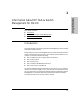
Accessing Hub Features Interpreting Device Status Accessing Hub Features Figure 6-1. Hub Status Overview Page Reading the Performance Gauges The performance gauges display statistical information about the selected device. By looking at the gauges, you can quickly determine if there are problems with the network utilization, collisions, the number of broadcasts per second, or the number of error packets. The gauges are refreshed every five seconds.
Accessing Hub Features Accessing Hub Features Interpreting Device Status Table 6-1. Gauge Attributes for Hubs Attribute Description Severity Values Utilization% Represents the traffic on the port as a percentage of the port’s bandwidth. Warning: 40% Critical: 75% Collisions% Represents the number of collisions that have occurred expressed as a percentage of the packets transmitted through the port.
Accessing Hub Features Configuring Your Device Table 6-2. Switching Hub Global Counters Description Total Octets Total number of octets of data (including bad packets) received on the network. This object can be used to estimate Ethernet utilization. Broadcast Packets Messages sent to all users on the network. Multicast Packets Multicast packets are delivered to a subset of users on the network, as opposed to Broadcast packets, which are sent to all users.
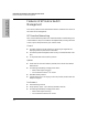
Accessing Hub Features Configuring Your Device Accessing Hub Features If the device you selected is not manageable by browser, you can only manage it from the management workstation. Figure 6-2. 10Base-T Hub-12M Device View You can enable and disable individual ports (click on the port to select it), or click on the Select All Ports button to enable or disable all the ports of a device in one step. For the switching hub, select a hub or card from the stack using the drop down list at the top.
Accessing Hub Features Configuring Your Device and faulty network interface cards. The Fault Detection page lets you set the sensitivity and actions that occur when a fault is detected on a port in your network. For hubs, you can set the sensitivity for logging network problems and disabling ports. The sensitivity settings are: High Sensitivity: the device will act when a network problem of any severity occurs. Network problems are automatically detected and entered into the Alert Log.
Accessing Hub Features Configuring Your Device Configuring IP Select the way that you want IP addresses configured for your network: ■ Manual - Set the IP address through the console. ■ Disabled - IP is disabled, there is no access to management or telnet. Not Recommended. ■ Use Bootp - The Bootp protocol sets the IP address automatically.
Accessing Hub Features Configuring Your Device Port Configuration The Port Configuration page displays information about the hub ports. To enable a port, select the port number in the page, then click Enable Selected Ports. Use the Disable Selected Ports button to disable a port or group of ports. The information displayed is described in the table. Table 6-3. Hub Port Configuration Description Port The port number. State The port can be on or off. Connected Yes: A device is connected to this port.
Accessing Hub Features Accessing Hub Features Configuring Your Device Figure 6-4. Setting Backup Links You can create one or more backup links by selecting the Backup Links button and clicking on the Add New Backup Link... button at the bottom of that page. The parameters are described in the table. Table 6-4. 6-10 Backup Link Parameters Parameter Description Status Displays which port is currently being used, a primary port or a backup port.
Accessing Hub Features Configuring Your Device Table 6-4. Backup Link Parameters Parameter Description Retries The maximum number of times the primary port can fail before the backup port becomes active. Configuring Load Balancing - Switching Hubs Configuration - Support URL You can obtain support information by going to the HP Support site on the World Wide Web. The URL is: http://www.hp.com/go/network_city Select Support. Figure 6-5.
Accessing Hub Features Configuring Your Device Accessing Hub Features If you want to change the URL that is accessed when the Support tab is selected, type in the new address and click on the Apply Changes button. For example, you could change the URL to launch your site home page.
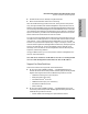
Managing Switches Switch Status 7 Managing Switches This chapter has information on: ■ Switch Status ■ Switch Identity ■ Configuration ■ Using VLANs ■ Support/Mgmt URL Switch Status To launch the Status - Overview page for a switch that is manageable by browser, double-click on the switch symbol in the HP Network Node Manager map or right-mouse-click on the symbol and select Monitor HP Hub/Switch.
Managing Switches Switch Status Figure 7-1. Switch Status Overview Page Managing Switches Graph Area The bar graph gives a quick overview of the performance of the switch. Each bar shows the highest percentage of transmitted (TX) or received (RX) traffic utilization for that port in the last five seconds. The graph area proportionally depicts three attributes for each port: ■ Unicast packets - The percent utilization for packets that were not addressed to a multicast or broadcast address.
Managing Switches Switch Status The graph only scales to 40% utilization. Network utilization above this level indicates serious performance problems. The graph also shows you if a port is active, disabled, or not connected. Alert Log Area - Find/Fix/Inform The “Find/Fix/Inform” capability of a device helps you proactively manage your network by displaying network traps and problem conditions in one easily accessible browser page.
Managing Switches Switch Status Status - Port Status The Port Status page (switches only) displays the operational status of each switch port. The settings can be changed in the Configuration - Port Configuration page. The Port Status settings are described in the following table. Managing Switches Table 7-1. 7-4 Port Status Settings Setting Description Port The port number. Port Type The network type of each switch port, for example, 100TX. Enabled Whether the port is enabled or disabled.
Managing Switches Identity Identity The Identity tab displays the following information about the switch:. ■ System Name ■ Product Number and Name ■ System Location ■ Firmware Version ■ System Contact ■ IP Address ■ System Up-Time ■ Management Server The Management Server field displays the address (URL) of the management station where HP Hub & Switch Management was installed. This can be changed by selecting the Configuration tab and displaying the Support/ Mgmt URLs page.
Managing Switches Configuration Figure 7-2. HP ProCurve Switch 8000M Device View Managing Switches Configuration - Fault Detection The automatic fault detection feature protects your network from failing because of problems such as network loops, defective cables, transceivers and faulty network interface cards. Network problems are automatically detected and entered in the Alert Log.
Managing Switches Configuration Configuration - System Information The System Information page lets you enter a system name for the device, the location of the device, and whom to contact in the event of a problem. Configuration - IP Configuration Select the way that you want IP addresses configured for your network: ■ Manual - Set the IP address through the console. ■ Disabled - IP is disabled, there is no access to management or telnet. Not Recommended.
Managing Switches Configuration Characteristics of Bootp and DHCP. The Bootp protocol is designed for a network in which each host has a permanent network location. It is not adaptable to a mobile computing environment. The Dynamic Host Configuration Protocol (DHCP) manages the allocation of TCP/IP configuration information by automatically assigning IP addresses.When a device connects to the network, it requests an address from the DHCP server.
Managing Switches Configuration Modify port settings Figure 7-4. Switch Port Configuration Switch Port Configuration Settings Setting Description Port The port number. The port may be appended with one of the following: • Trkx - The port trunk to which this port belongs • Mesh - The port has been assigned to a switch mesh domain • MP - The port is a Monitor Port Port Type The MAC layer type, for example, 100VG or FDDI. Enabled Whether the port is enabled or disabled.
Managing Switches Configuration Table 7-2. Switch Port Configuration Settings Setting Description Flow Control Indicates the current state of flow control for this port. When disabled, the port does not generate flow control packets and drops any flow control packets it receives. • 10/100TX, 10FL, 100FX: – On - Flow control is enabled. – Off - Flow control is disabled (default). • Gigabit: – On (TX, RX) - Flow control is enabled on transmit and receive. – On (RX) - Flow control on receive only.
Managing Switches Configuration Figure 7-5. Selecting a Monitoring Port on a Switch Using VLANS As networks expand, more routers are needed to separate users into broadcast domains. Latency degrades network performance, and is a special problem for multimedia applications. Switches using VLANS create the same division of the network into broadcast domains, but do not have the latency problems of a router. Switches are also a more cost-effective solution.
Managing Switches Configuration VLANs make large networks more manageable. You can group users according to some shared characteristic, such as a common business function or a common protocol. A single switch may have several independent VLANs within it. Note: VLANs must be created with the device console.
Managing Switches Configuration Enabling Broadcast Control for IP The IP protocol uses Address Resolution Protocol (ARP) packets to find the MAC address of a node that corresponds to the network layer address. When Broadcast Control is enabled, the switch intercepts the ARP packet on its way to the destination node. If this destination is unknown to the switch, the switch floods the ARP request to all ports.
Managing Switches Configuration environment (where more than one IP network is configured in a single broadcast domain). See Routing Information Protocol. Internet Group Management Protocol (IGMP) Multimedia and email applications need the ability to communicate to multiple destinations efficiently. IP multicasting allows hosts to dynamically register for sending or receiving multicast traffic.
Managing Switches Configuration Note: Using the console you can designate specific ports to always or never forward multicast packets. Forward with High Priority When “Forward with High Priority” is checked, any IGMP packets received by the switch will be forwarded in a prioritized manner, preceding packets with normal priority. The Spanning Tree Protocol The Spanning Tree Protocol (IEEE 802.1d) maintains a loop-free topology in networks with redundant bridges or switches.
Managing Switches Configuration If you have configured VLANs for the switch (you must do this with the device console), select a VLAN for which the features will apply. Configuration - Support/Mgmt URLs Support URL To go directly to the HP Support Site on the World Wide Web, click on the Support tab. You will launch the site indicated by the URL that has been entered in the Configure - Support/Mgmt URLs page. By default this is the HP Network City support site.
Managing Switches Configuration Management Server URL Enter the URL for your management server. This will let you display the online help at any client in the network. Note: This field will contain the address for the HP Network City web site by default. If you do not change it, the online help will be loaded from the HP Network City site.
Managing Switches Managing Switches Configuration 7-18
Setting Up Security for a Device Device Passwords 8 Setting Up Security for a Device It is advisable to set up security for your devices to prevent unauthorized access to the device or the network. You can configure device security to prevent unauthorized use of certain parts of the network by certain nodes, and to keep unwanted traffic out of certain parts of the network.
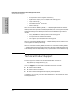
Setting Up Security for a Device Device Passwords Figure 8-1. Assign Passwords to a Device There are two categories of passwords: ■ Operator (Read only): The Operator can view all pages except the Security pages. For switches, this password is the same as the console password. ■ Manager (Full Read and Write permissions): The Manager can view all pages and make any changes in any page.
Setting Up Security for a Device Device Passwords Table 8-1. Manager/Operator Password Combinations Passwords Read Protected Write Protected Results Manager password set Operator password not set N/A Yes Anyone can get Read Access, but only the Manager can read and write to the device. Recommended minimum setting. Manager password set Operator password set Yes Yes Both the Manager and the Operator have Read Access, but only the Manager has Write Access. Everyone else is shut out of the device.
Setting Up Security for a Device Port Security (hubs only) Port Security (hubs only) You can assign security levels on hubs port by port. Select the Port Security button to view the current settings for each port. This feature is not available for switches. Figure 8-2. View the Security Settings for Each Port. Address Selection Address Selection refers to how the authorized address for a port is discovered. The three settings are explained in the table. Setting Up Security for a Device Table 8-2.
Setting Up Security for a Device Port Security (hubs only) Table 8-2. Address Selection Setting Description First Heard The device learns the address of the device attached to the port and makes it the authorized MAC address. If a different device is later attached to the port, the new address is registered as an “intruder address”; a security violation has occurred and the port is automatically disabled. Assigned Enter the address of the device that is authorized to be attached to the port.
Setting Up Security for a Device Port Security (hubs only) Note: In order for traps to function, you must also set the trap in the Thresholds dialog box, as follows: 1. Using the right mouse button, click on the device symbol in the HP Network Node Manager map. 2. Select SNMP Configuration. 3. Select the Thresholds tab and set the thresholds for the traps you are interested in receiving. 4. Select the Trap Receivers tab and set the management stations that can capture traps. 5.
Setting Up Security for a Device Set Security Policy for Selected Ports (hubs only) port will not be disabled when a new address is learned if the setting is Continuous. Set Security Policy for Selected Ports (hubs only) You can set the security policy port by port, or by selecting a group of ports. Select one port by clicking on the entry in the Port Security page.
Setting Up Security for a Device Setting Up Security for a Device The Intrusion Log (hubs only) 8-8 ■ Intruder Address - Address of the intruder. The IP address is displayed for SNMP agent violations. The MAC address is displayed for port violations. The port violation must be cleared before another port violation will display. ■ Date/Time - Date and time the security intrusion occurred.
Performing Diagnostics Performing a Ping/Link Test Performing Diagnostics Using HP Hub & Switch Management, you can help isolate faults by running device self-tests, Link tests, and Ping tests (IP networks). Note: For older HP devices that cannot be managed with a Web browser, read the chapter “Management for Non-Browserable Devices” or see the online help.
Performing Diagnostics Performing Diagnostics Rebooting a Device Figure 9-1. Ping/Link Test The number of successes or failures of the test packets reaching the Destination IP or MAC Address are displayed at the top of the page. A failure means that either the device at the destination address did not respond within the timeout specified, or the data returned from the device indicated an error.
Performing Diagnostics Resetting a Hub to Factory Default Settings Resetting the hub to the factory default settings removes any configuration changes that you have made since installing the device, and restores the factory defaults. The IP address is also removed; you must enter an IP address before the device will operate on your network, unless you have Bootp or DHCP. Producing a Configuration Report The Configuration Report displays information about the current settings on your device.
Performing Diagnostics Performing Diagnostics Producing a Configuration Report 9-4
10 HP Hub & Switch Management Admin HP Hub & Switch Management Admin is an administration utility that allows you to set specified configuration and control parameters used by HP Hub & Switch Management for OV-UX. HP Admin is automatically installed when you install HP Hub & Switch Management for OV-UX.
HP Hub & Switch Management Admin HP Admin Parameters The parameters are briefly described below. For more information, see the HP Admin online help. Network Parameters HP Hub & Switch Management Admin Network parameters enable you to set values and behavior for network device communication and Closeup View activity. The parameters for network device communication are described in the following table. Figure 10-1. Setting Network Parameters Table 10-1.
HP Hub & Switch Management Admin HP Admin Parameters the attached devices appears. When the device symbol is in the executable state (a box appears around the symbol) and you double-click on it, a Closeup View of the device appears. Note: When an HP Admin check box is disabled, no change in the existing device symbol state occurs when OpenView is restarted.
HP Hub & Switch Management Admin HP Admin Parameters HP Hub & Switch Management Admin Table 10-2. User Interface Parameters 10-8 Parameter Description User Level • This parameter controls HP Hub & Switch Management messages to the user. There are 3 user-level parameters: • Beginner (User Level 1, default): Message boxes will notify the user when device parameter modifications have completed. Also, the user will be warned about changes that are about to be made to a device or to a local file.
HP Hub & Switch Management Admin HP Admin Parameters Graph Options Parameters HP Admin graph options parameters enable you to control different aspects of the graphing feature. The parameters are described in the following table. Table 10-3. Graph Option Parameters Description Graph Log Format This parameter allows you to choose the format of the information logged to a graph log file from the Graph Counters function. • Text: Data will be logged to the log file as straight ASCII text.
HP Hub & Switch Management Admin HP Admin Parameters Printer Configuration Parameters HP Hub & Switch Management Admin Network management applications that implement printer support on X Window systems can use the Print Configuration dialog box to configure printer configuration parameters. Figure 10-2. Printer Configuration Table 10-4. Printer Configuration Parameters 10-10 Parameter Description Default Printer Displays the current default printer name.
HP Hub & Switch Management Admin HP Admin Parameters Table 10-4. Printer Configuration Parameters Description Set As Default Sets the printer selected in the “Installed Printers” box as the default printer. Remove Removes a selected printer from the “Installed Printers” list. Add Displays a list of supported printers that you can select and add to the “Installed Printers” list.
HP Hub & Switch Management Admin HP Hub & Switch Management Admin HP Admin Parameters Figure 10-3. OpenView Configuration Options The options are described in more detail here. ForceMapUpdates. If the attributes (name of icon, application name) of a symbol are changed, for example, during an update, the symbol must be reregistered with OpenView for the changes to take effect. Selecting this option will update the symbol the next time that the master copy of OpenView (ovw) is run.
HP Hub & Switch Management Admin HP Admin Parameters Distributed Console. HP Hub & Switch Management is started remotely when you use Network Node Manager’s Distributed Console feature from a client station. The program “ovexec” displays a pop-up window in which you enter a password for the remote system. If you do not want this pop-up to be displayed, that is, you do not wish to enter a password, select the “remsh” option to start HP Hub & Switch Management remotely.
HP Hub & Switch Management Admin HP Hub & Switch Management Admin HP Admin Parameters 10-14
11 Management for Non-Browserable Devices This chapter provides a summary of hub, bridge, and switch management functions for devices that cannot be managed with the Web browser interface. It includes the following topics: ■ About Closeup Views ■ Overview of Toolbar Functions Use the online help for more information about specific device functions. About Closeup Views A Closeup View is an interactive, visual display of a device.
Management for Non-Browserable Devices About Closeup Views Displaying the Closeup View You can display a Closeup View in several ways, including the following: From an HP OpenView map, use the left mouse button and double-click on a hub, bridge, or switch symbol. ■ On an HP OpenView map, select a hub, bridge, or switch symbol. Then display the Monitor menu and select HP Hub/Switch.
Management for Non-Browserable Devices About Closeup Views The number of Closeup Views that you can display at one time depends on your free system resources available (such as available memory). If the HP device can be managed with your browser, the menu option SNMP Configure HP Hub/Switch will also display when you right-mouse-click on a device symbol. Selecting this feature allows you to configure community names and authorized managers for the device. See the online help for configuration instructions.
Management for Non-Browserable Devices Overview of Toolbar Functions Hub LAN Ports The Closeup View allows you to view each hub port and determine port status. Port status can be determined by the port icon symbol and colors displayed. You can individually select any port on a Closeup View by clicking on the port itself. The port number will be displayed in the message bar. If you select a port, you can perform management functions through the applicable Toolbar button.
Management for Non-Browserable Devices Overview of Toolbar Functions Table 11-1. Summary of Toolbar Functions Icon Description Port Statistics Displays gauges for viewing statistical counters for a segment and selected ports on the segment. • Hubs: gauges for LAN Activity, Error Packets, and Broadcast Packets are displayed. • Bridges: gauges for Broadcast Packets, Packets Forwarded, Packets Filtered, and Error Packets are displayed.
Management for Non-Browserable Devices Overview of Toolbar Functions Table 11-1. Summary of Toolbar Functions Management for NonBrowserable Devices Icon 11-6 Toolbar Button Description Diagnose Displays a pop-up menu list of device or network test functions. The tests that can be performed depend on the type of device. Security Displays a tabbed dialog box for configuring security: • Authorized Managers: The network management stations that can send and receive SNMP requests for this device.
Management for Non-Browserable Devices Overview of Toolbar Functions Table 11-1. Summary of Toolbar Functions Icon Description Properties Displays a dialog box that allows you to view or change information about a selected VLAN or segment: • Port number • Name of VLAN • Connected status • Enabled/Disabled status • Active status • Protocol type Large icons Displays ports as large icons. Small icons Displays ports as small icons. List Lists all port icons in rows.
Management for Non-Browserable Devices Overview of Toolbar Functions Configuration Functions The Configuration button displays a menu that allows you to perform configuration functions for the device. The menu items displayed depend on the type of device. See the online help for details about the Configuration menu items. Setting the Configuration Parameters Management for NonBrowserable Devices When you select the Configuration icon, the Configuration tabbed dialog box displays.
Appendix A Agent Firmware Versions A Appendix A Appendix A contains the following topics: ■ Agent Firmware Versions ■ Preparing Network Devices ■ Globally Assigned IP Network Addresses ■ Configuring IP Parameters Agent Firmware Versions HP Hub & Switch Management communicates with network devices using SNMP (Simple Network Management Protocol).To access device features, each network device must contain a compatible version of agent software or firmware.
Appendix A Preparing Network Devices For HP devices, use an existing version of HP Hub & Switch Management or other device management utility. Update the device’s software or firmware to the current supported version. Note: HP Hub & Switch Management may be able to discover devices that have previous versions of device agent firmware. However, the use of some functions may be limited.
Appendix A Configuring IP Parameters bridge. Globally Assigned IP Network Addresses If you intend to connect your network to other networks that use globally administered IP addresses, Hewlett-Packard strongly recommends that you use IP addresses that have been assigned to you. There is a formal process for assigning unique IP addresses to networks worldwide. Contact one of the following companies: United States and countries not in Europe or Asia/Pacific Network Solutions, Inc.
Appendix A Configuring IP Parameters The network management station is configured for IP using the TCP/IP stack utilities. To configure a device for IP, you typically connect to the device’s console port and use the console port interface. (Refer to the device’s instal lation manual for more information.) Before you configure the network management station and manageable devices for IP, make a list of all the devices on the network and what their IP addresses will be.
Appendix A Configuring IP Parameters name “public” on the device to allow the device to be discovered and managed by HP Hub and Switch Management. Typically, the community name on HP hubs and bridges will automatically default to “public”. To configure a device for IP networks, use the device’s console port interface. Refer to the device’s Installation and Reference Guide for use of the device’s RS-232 console port.
Appendix A Appendix A Configuring IP Parameters A-6
Index A Acknowledge Alerts … 5-5 Add New Backup Link … 6-10 Address Resolution Protocol … 7-12 Address Selection … 8-4 agent software … A-1 agent system … 3-3 Alert Log … 5-3, 7-3 alerts … 6-2 closing … 5-4 first time install information … 5-6 Alerts page … 7-3 ARP … 7-13 ARP, cache … 7-12–7-13 Assign an Address … 8-5 attributes, setting … 10-7 Authorized Address … 8-5 Automatic Broadcast Control … 7-12 Automatic IP RIP Control … 7-13 Automatic IPX RIP/SAP Control … 7-13 B Backup Link … 6-9 backup port … 6
Device ID, defined … 11-4 Device View … 6-5 devices, chained … 3-4 DHCP … 7-8 Diagnose defined … 11-6 disable port … 8-6 Disable Port, defined … 11-6 Disable Selected Ports … 6-9 DISPLAY variable, X Windows … 4-2 Distributed Console … 10-11, 10-13 Dynamic Host Configuration Protocol (DHCP) … 6-8, 7-8 E eavesdrop prevention … 8-5 Enable Graph Sensitive Scaling … 10-9 Enable Selected Ports … 6-9 Enable/Disable Port, defined … 11-6 Errors% … 6-4 executable … 10-6 explodable … 10-6 F Fault Detection … 5-5 fau
Management Server setting URL … 7-17 manager SNMP manager system … 3-3 Manager, with password … 8-2 Modify Selected Ports … 7-8 monitor port … 7-10 Move Selected Ports … 6-6 multicast packets … 6-5 queriers … 7-14 traffic … 7-14 multicasts … 6-4 N Network Node Manager description … 3-3 NoMapWalk … 10-11–10-12 NSQ … 7-12 O OpenView description … 3-2 Network Node Manager … 3-2 starting on HP-UX 10.
security defined … 11-6 intrusions … 8-7 policy … 8-7 violation … 6-9 Select All Ports … 6-6 Send Alarm … 8-5 sensitivity … 6-7, 7-6 high … 5-5, 6-7 low … 5-5, 6-7 medium … 5-5, 6-7 threshold level … 5-4 Service Advertising Protocol … 7-13 Set As Default, printer … 10-11 Set Security Policy … 8-5 set, SNMP request … 3-3 Show Tool Bar Banner … 10-8 SNMP … 3-1, 3-3, A-1 AdvanceStack modules … 3-6 community name … 3-3, A-4 concepts … 3-2 Get/Set requests … 3-3 management platform description … 3-3 SNMP Max Ret