
Manual

DISASSEMBLY PROCEDURE:
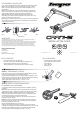
If you wish to disassemble the crankarm please follow the following steps
001: On the drive side fully unscrew the shaft end cap using a 10mm
Allen key and the tapered plug using the crankset assembly tool and
19mm socket.
002: On the non drive side unscrew the bearing preload nut pinch bolt
using a 2.5mm Allen key and then screw out the bearing preload nut to
maximise the gap between the bearing shield and preload nut.
003: If possible, slide the crankset extraction spacer into the gap.
+LWLUKPUNVU[OLIV[[VTIYHJRL[JVUÄN\YH[PVU[OLZWHJLYTH`VYTH`
UV[Ä[PU0MP[KVLZUV[Ä[TV]L[V
004: Using the crankset extraction spanner, screw in the bearing preload nut.
This will pull out the non drive side arm sub assembly (arm and shaft) and
extract the drive side arm.
WARRANTY:
All Hope Technology components are covered for two years from original date of purchase
against manufacturer defects in material and workmanship.
Proof of purchase is required. Products must be returned to the original place of purchase or to
/VWL;LJOUVSVN`[VWYVJLZZHU`^HYYHU[`JSHPT7SLHZLWYPU[HUKÄSS[OL¸NVVKZYL[\YULKMVYT¹
found on the tech support section of our website should you wish to send a product back.
This warranty does not cover any damage caused through normal wear, mis-use or failing
[VJVTWS`I`[OLYLJVTTLUKH[PVUZNP]LU;OPZ^HYYHU[`KVLZUV[HɈLJ[`V\YZ[H[\[VY`YPNO[Z
002: 003:
MAXIMISE GAP
004:001:
HOPE TECHNOLOGY
Hope Mill
Barnoldswick,
Lancaashire
BB18 5PX, United Kingdom
info@hopetech.com hopetech.com
INSTALLATION GUIDE
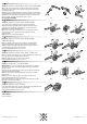
STEP 1: PRELIMINARY CHECKS
Firstly make sure you are using the right bottom bracket for the crankset -
the bearing internal diameter must be 30mm diameter.
The other critical dimension is the over bearing width (d in diagram) of the
IV[[VTIYHJRL[VUJLÄ[[LK[V[OLMYHTL;OPZZOV\SKTLHZ\YL[OLMVSSV^PUN!
TTZOHM[\ZLKPUTTMYHTLZ TTTT
TTZOHM[\ZLKPUTTMYHTLZTTTT
BOX CONTENTS:
5VUKYP]LZPKLJYHURHYTZ\IHZZLTIS`
+YP]LZPKLJYHURHYTZ\IHZZLTIS`Ä[[LK^P[OZWPKLYVYUV[
*OHPUYPUNIVS[ZZWPKLY[HIJV]LYZWLKHS^HZOLYZ
;VVSZL[HZZLTIS`[VVSL_[YHJ[PVUZWHUULYL_[YHJ[PVUZWHJLY
STEP 2: INSTALL SPIDER/SPIDERLESS
CHAINRING AND CHAINRING
If not already installed, install the crankset spider or spiderless chainring
HZMVSSV^Z!
001: Make sure the drive side crankarm to spider interface is clean, free
of dust and dirt. Apply a small amount of grease on the spline and thread.
002: Install the spider or spiderless chainring onto the driving spline,
making sure the orientation of the spider is correct. Fit the lockring shim
HUKLUNHNL[OLSVJRYPUNI`OHUKVU[OLÄYZ[[OYLHKZ
Do not use the lockring tool at this point, the lockring should thread on
LHZPS`Q\Z[\ZPUN`V\YÄUNLYZ
003:-PUHSS`\ZPUN[OLZWLJPÄJSVJRYPUN[VVSYLM/*;[PNO[LU[OL
SVJRYPUN;VKVZV`V\JHULP[OLY\ZLHZ[K))ZWHUULYTTZVJRL[VY
place the tool upside down in a vice.
9LJVTTLUKLK[PNO[LUPUN[VYX\L!5T
Following manufacturer instructions, if needed, at this point install the
chainring onto the spider. Use the hardware provided and if you aren’t using
a bashring use the spider tab covers on the outside face of the spider.
*OHPUYPUNIVS[ZYLJVTTLUKLK[PNO[LUPUN[VYX\L!5T
TOOLS REQUIRED:
*YHURZL[ZWLJPÄJ[VVSZL[WYV]PKLK
TTZWHUULYHUK TTZVJRL[
TT(SSLURL`
TT(SSLURL`
;VYX\L^YLUJO
d
1mm