Service Manual Self-Contained Cubelet Models C-80BAJ C-80BAJ-DS C-80BAJ-AD C-80BAJ-ADDS hoshizakiamerica.
WARNING Only qualified service technicians should install and service the appliance. To obtain the name and phone number of your local Hoshizaki Certified Service Representative, visit www.hoshizaki.com. No service should be undertaken until the technician has thoroughly read this Service Manual. Failure to service and maintain the appliance in accordance with this manual will adversely affect safety, performance, component life, and warranty coverage and may result in costly water damage.
IMPORTANT This manual should be read carefully before the appliance is serviced. Read the warnings and guidelines contained in this manual carefully as they provide essential information for the continued safe use, service, and maintenance of the appliance. Retain this manual for any further reference that may be necessary. CONTENTS Important Safety Information.................................................................................................. 4 I.
Important Safety Information Throughout this manual, notices appear to bring your attention to situations which could result in death, serious injury, damage to the appliance, or damage to property. WARNING Indicates a hazardous situation which could result in death or serious injury. NOTICE Indicates a situation which could result in damage to the appliance or property. IMPORTANT Indicates important information about the use and care of the appliance.
WARNING, continued • Do not place fingers or any other objects into the ice discharge opening. • The appliance is not intended for use by persons (including children) with reduced physical, sensory, or mental capabilities, or lack of experience and knowledge, unless they have been given supervision or instruction concerning use of the appliance by a person responsible for their safety. • Young children should be properly supervised around the appliance.
NOTICE, continued • Keep ventilation openings, in the appliance enclosure or in the built-in structure, clear of obstruction. • Do not place objects on top of the appliance. • The storage bin is for ice use only. Do not store anything else in the storage bin.
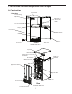
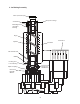
I. Construction and Water/Refrigeration Circuit Diagram A. Construction Top Panel 1.
2.
3.
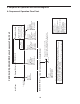
BC open Comp de-energized FM de-energized GM de-energized LFS closed UFS closed FT resets Comp continues FM continues GM continues WV de-energized Legend: BC-bin control Comp-compressor DV-drain valve DP-drain pump (optional) FM-fan motor FT-fill timer (time delay relay) GM-gear motor LFS-lower float switch UFS-upper float switch WV-inlet water valve UFS open FT exceeded WV continues Comp de-energized FM de-energized GM de-energized 90 sec.
B. Service Diagnosis WARNING • This appliance should be diagnosed and repaired only by qualified service personnel to reduce the risk of death, electric shock, serious injury, or fire. • Risk of electric shock. Use extreme caution and exercise safe electrical practices. • Moving parts (e.g., fan blade) can crush and cut. Keep hands clear. • CHOKING HAZARD: Ensure all components, fasteners, and thumbscrews are securely in place after the appliance is serviced.
3) After all of the water has drained, move the control switch to the "OFF" position, then unplug the appliance. 4) Remove the front panel, louver, and upper and lower rear panels. 5) Remove the screws securing the control box, then gently pull out the control box and secure it in a safe position. Remove the control box cover. 6) Plug the appliance back into the electrical outlet. 7) Startup/Fill Cycle–Move the control switch to the "ICE" position. With LFS and UFS open, WV energizes.
GM Diagnosis: Check that GM energizes. If not, check for 115VAC at GM. If 115VAC is not present, check GM external protector on front of control box. If tripped, reset. If it does not reset, replace GM external protector. Once reset, if GM does not energize, check GM windings (internal protector) and GM capacitor. If GM starts but the auger does not turn, check coupling between auger and GM. FM Diagnosis: Check that FM energizes. If not, check for 115VAC at FM red (R) wire to neutral (W).
C. Bin Control Check BC shuts down the icemaker within 10 sec. when ice contacts the thermostatic bulb, regardless of the cycle at activation. NOTICE When the ambient temperature is below 45°F (7°C), BC opens and shuts down the appliance even if the ice storage bin is empty. When BC is set in the prohibited range, the appliance operates continuously even if the ice storage bin is filled with ice. Setting in the prohibited range may result in appliance and property damage.
D. Float Switch Check and Cleaning 1. Float Switch Check 1) Move the control switch to the "DRAIN" position. 2) Remove the upper rear panel. 3) Allow the water system to drain for 1 min. 4) Move the control switch to the "OFF" position, then unplug the appliance from the electrical outlet. 5) Remove bell connectors from FS black (BK), blue (BU), and red (R) wires. Check continuity between black (BK) (common) and red (R) (UFS) and between black (BK) (common) and blue (BU) (LFS).
6) Rinse FS assembly thoroughly with clean water and replace in its correct position. 7) Replace the upper rear panel in its correct position. 8) Plug the appliance into the electrical outlet, then move the control switch to the "ICE" position to start the automatic icemaking process. Legend: FS–float switch; LFS–lower float switch; UFS–upper float switch Float Switch Assembly Reservoir Cover Reservoir Fig.
E. Optional Drain Pump HS-5061 1. Overview As ice melts, water drains from the storage bin into DP. LFS closes. Nothing happens at this time. UFS closes, DP energizes and pumps out the water. UFS opens, nothing happens at this time. LFS opens, DP de-energizes. If water cannot be pumped out of DP due to a blocked discharge hose, bad check valve, or bad DP motor, water level continues to rise and SFS closes. DP continues and appliance de-energizes. Power is supplied to DP motor as long as LFS is closed.
F. Diagnostic Tables 1. No Ice Production No Ice Production - Possible Cause Startup/Fill Cycle 1. Power Supply a) Unplugged, off, blown fuse, or tripped breaker. b) Not within specifications. 2. Optional Drain Pump HS-5061 a) Drain pump connection unplugged or loose. b) Drain pump safety float switch open. 3. Control Switch a) "OFF" position. b) Bad contacts. 4. Bin Control Thermostat Assembly a) Open with bin filled with ice. (with integrated heater) b) Out of position. c) Out of adjustment.
Refill 1. Float Switch See "II.D. Float Switch Check and Cleaning." a) Dirty/sticking. 2. Inlet Water Valve a) Screen or orifice clogged. 3. Water Supply a) Water supply off or improper water pressure (7 to 113 PSIG). b) Defective. b) Defective. b) External water filters clogged. 4. Water Control Relay a) Defective. 5. Time Delay Relay a) Defective. Shutdown 1. Bin Control Thermostat Assembly a) Open with bin filled with ice. (with integrated heater) b) Out of position. c) Out of adjustment.
III. Controls and Relays The C-80BAJ(-C) utilizes a control switch, time delay relay, water control relay, and compressor relay to control operation. A. Control Switch The control switch has 3 positions, "OFF," "ICE," and "DRAIN." a) "OFF": All components except the optional drain pump are de-energized when the control switch is in the "OFF" position. The optional drain pump circuit remains energized when the control switch is in the "OFF" position.
IV. Refrigeration Circuit and Component Service Information WARNING • This appliance should be diagnosed and repaired only by qualified service personnel to reduce the risk of death, electric shock, serious injury, or fire. • Move the control switch to the "OFF" position, then unplug the appliance from the electrical outlet before servicing. • CHOKING HAZARD: Ensure all components, fasteners, and thumbscrews are securely in place after the appliance is serviced.
2. Brazing WARNING • R-134a itself is not flammable at atmospheric pressure and temperatures up to 212°F (100°C). • R-134a itself is not explosive or poisonous. However, when exposed to high temperatures (open flames), R-134a can be decomposed to form hydrofluoric acid and carbonyl fluoride both of which are hazardous. • Do not use silver alloy or copper alloy containing arsenic. 1) Braze all fittings while purging with nitrogen gas flowing at a pressure of 3 to 4 PSIG.
6) A liquid charge is required when charging an R-134a system. Place the service cylinder on the scales; if the service cylinder is not equipped with a dip tube, invert the service cylinder, then place it on the scales. Open the high-side valve on the gauge manifold. 7) Allow the system to charge with liquid until the proper charge weight is met. 8) Close the high-side valve on the gauge manifold, then close the refrigerant access valve (if applicable). Disconnect the gauge manifold hose.
B. Component Service Information NOTICE • When replacing a component listed below, see the notes to help ensure proper operation. • When replacing evaporator assembly and water circuit components, make sure there are no water leaks after the repair is complete. Component Notes Extruding Head • Seal bolts must be replaced once removed because seal material is one-time use only. • If new seal bolts do not have preapplied threadlocker, apply Loctite 243 or equivalent threadlocker to seal bolt threads.
Evaporator Assembly Thumbscrew Seal Bolts Inspect for leakage around seal bolts. Tighten (11.1 ft-lb/15 N·m) or replace as necessary. Seal bolts must be replaced once removed because seal material is one-time use only. If new seal bolts do not have preapplied threadlocker, apply Loctite 243 or equivalent threadlocker to seal bolt threads.
1. Upper Bearing Wear Check To ensure that the bearing inside the extruding head does not exceed the wear tolerance of .02", follow the instructions below. 1) Move the control switch to the "OFF" position, then unplug the appliance from the electrical outlet. 2) Remove all ice from the storage bin. 3) Remove the top panel. See Fig. 4. 4) Remove the spout and packing. 5) Remove the cutter. 6) Grasp the top of the auger and move the auger towards you and then try to insert a .
2. Removal and Replacement of Extruding Head 1) Close the water supply line shut-off valve. 2) Move the control switch to the "DRAIN" position. 3) Allow the water system to drain for 1 minute. 4) Remove all ice from the storage bin. 5) After all of the water has drained, move the control switch to the "OFF" position. Unplug the appliance from the electrical outlet. 6) Remove the top panel. See Fig. 4. 7) Remove the spout and packing. 8) Loosen the cutter (do not remove).
3. Removal and Replacement of Auger 1) Close the water supply line shut-off valve. 2) Move the control switch to the "DRAIN" position. 3) Allow the water system to drain for 1 minute. 4) After all of the water has drained, move the control switch to the "OFF" position. Unplug the appliance from the electrical outlet. 5) Remove all ice from the storage bin. 6) Remove the top panel. See Fig. 4. 7) Remove the spout and packing.
4. Removal and Replacement of Evaporator NOTICE • Always install a new drier every time the sealed refrigeration system is opened. Do not replace the drier until after all other repair or replacement has been made. • When brazing, protect the drier by using a wet cloth to prevent the drier from overheating. Do not allow the drier to exceed 250°F (121°C). 1) Close the water supply line shut-off valve. 2) Move the control switch to the "DRAIN" position. 3) Allow the water system to drain for 1 minute.
21) Use an electronic leak detector or soap bubbles to check for leaks. Add a trace of refrigerant to the system (if using an electronic leak detector), and then raise the pressure using nitrogen gas (140 PSIG). Do not use R-134a as a mixture with pressurized air for leak testing. 22) Evacuate the system, then charge it with refrigerant. See the nameplate for the required refrigerant charge. 23) Reattach and secure the reservoir outlet hose.
9) Grasp the cutter and carefully lift out the extruding head. 10) Grasp the auger and carefully lift it out. When pulling out the auger, the upper part of the mechanical seal should come out with it. 11) Remove the socket head cap screws securing the evaporator to the lower housing. 12) Raise the evaporator up to access the lower housing. 13) The mechanical seal consists of two parts. One moves along with the auger, and the other is fixed on the lower housing.
28) Replace the upper rear panel and top panel in their correct positions. 29) Plug the appliance into the electrical outlet, then move the control switch to the "ICE" position to start the automatic icemaking process. 6. Removal and Replacement of Gear Motor NOTICE! Hoshizaki recommends that the gear motor capacitor be replaced at the same time as the gear motor. 1) Close the water supply line shut-off valve. 2) Move the control switch to the "DRAIN" position.
V. Maintenance The appliance must be maintained in accordance with the instruction manual and labels provided. Consult with your local Hoshizaki Certified Service Representative about maintenance service. WARNING • Only qualified service technicians should service the appliance. • To reduce the risk of electric shock, do not touch the control switch with damp hands. • Before Servicing: Move the control switch to the "OFF" position.
A. Maintenance Schedule The maintenance schedule below is a guideline. More frequent maintenance may be required depending on water quality, the appliance's environment, and local sanitation regulations. Maintenance Schedule Frequency Area Weekly Monthly Every 3 Months Every 6 Months Yearly Task Scoop Clean the scoop using a neutral cleaner. Rinse thoroughly after cleaning. Drain the Appliance Move the control switch to the "DRAIN" position. Allow the water system to drain for 1 minute.
VI. Preparing the Appliance for Periods of Non-Use During extended periods of non-use, extended absences, or in sub-freezing temperatures, follow the instructions below. When the appliance is not used for two or three days under normal conditions, it is sufficient to move the control switch to the "OFF" position. WARNING Only qualified service technicians should service the appliance.
14) Plug the appliance back in, then move the control switch to the "DRAIN" position. 15) Blow out the reservoir outlet hose using the compressed air or carbon dioxide supply. 16) Move the control switch to the "OFF" position, then unplug the appliance from the electrical outlet. 17) Reconnect the reservoir outlet hose to the reservoir, then secure with the clamp. Make sure all hoses are connected and secure. 18) Replace the rear panel in its correct position.
VII. Disposal The appliance contains refrigerant and must be disposed of in accordance with applicable national, state, and local codes and regulations. Refrigerant must be recovered by properly certified service personnel.
VIII. Technical Information A. Specification and Performance Data 1.
B. Wiring Diagrams 1.
2.