
Service Manual


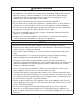
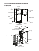
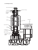

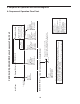
Table Of Contents
- Important Safety Information
- I. Construction and Water/Refrigeration Circuit Diagram
- II. Sequence of Operation and Service Diagnosis
- III. Controls and Relays
- IV. Refrigeration Circuit and Component Service Information
- V. Maintenance
- VI. Preparing the Appliance for Periods of Non-Use
- VII. Disposal
- VIII. Technical Information

10
II. Sequence of Operation and Service Diagnosis
A. Sequence of Operation Flow Chart
2. Freeze Cycle
Control Switch "ON"
LFS closed
UFS closed
Comp energized
FM energized
GM energized
WV de-energized
UFS open
LFS open
FT starts (90 sec.)
Comp continues
FM continues
GM continues
WV energized
UFS open
LFS open
WV energized
1. Startup/Fill Cycle
LFS closed
UFS closed
FT resets
Comp continues
FM continues
GM continues
WV de-energized
Low Water Safety
UFS open
FT exceeded
WV continues
Comp de-energized
FM de-energized
GM de-energized
Rell
Maximum 90 sec.
When rell is achieved
(UFS closed) icemaker
restarts at 2. Freeze Cycle.
C-80BAJ(-DS)(-AD)(-ADDS) Series Sequence Flow Chart
Startup
Shutdown & Restart
1. Bin Full Icemaker Off
BC open
Comp de-energized
FM de-energized
GM de-energized
Legend:
BC-bin control
Comp-compressor
DV-drain valve
DP-drain pump (optional)
FM-fan motor
FT-ll timer (time delay relay)
GM-gear motor
LFS-lower oat switch
UFS-upper oat switch
WV-inlet water valve
• Optional Drain Pump HS-5061
Drain pump has 115VAC when appliance is plugged into electrical outlet.
115VAC remains at drain pump until appliance is unplugged from the electrical outlet.
• Control Switch in the "DRAIN" Position
When the control switch is in the "DRAIN" position, 115VAC is supplied to the drain valve.
2. Icemaker Restart
BC closed
Cycle Steps
90 sec. FT exceeded
Restart is based on position of UFS
a. If UFS is closed, restart begins at 2. Freeze Cycle
b. If UFS is open, restart begins at 1. Startup/Fill Cycle