Hoshizaki Hoshizaki America, Inc. Commercial Series Refrigerated Kitchen Equipment Models Reach-In B-Series “A Superior Degree of Reliability” SERVICE MANUAL www.hoshizaki.
WARNING Only qualified service technicians should install and service the appliance. To obtain the name and phone number of your local Hoshizaki Certified Service Representative, visit www.hoshizaki.com. No service should be undertaken until the technician has thoroughly read this Service Manual. Failure to service and maintain the equipment in accordance with this manual will adversely affect safety, performance, component life, and warranty coverage.
IMPORTANT This manual should be read carefully before the appliance is serviced. Read the warnings and guidelines contained in this booklet carefully as they provide essential information for the continued safe use, service, and maintenance of the appliance. Retain this booklet for any further reference that may be necessary. CONTENTS Important Safety Information.................................................................................................. 5 I. Specifications............................
V. Replacement of Components........................................................................................... 39 A. Service for Refrigerant Lines........................................................................................ 39 1. Refrigerant Recovery.............................................................................................. 39 2. Brazing................................................................................................................... 40 3.
Important Safety Information Throughout this manual, notices appear to bring your attention to situations which could result in death, serious injury, or damage to the appliance or damage to property. WARNING Indicates a hazardous situation which could result in death or serious injury. NOTICE Indicates a situation which could result in damage to the appliance or property. IMPORTANT Indicates important information about the use and care of the appliance.
WARNING, continued • 208-230VAC: This appliance is equipped with a NEMA L14-20 four-prong locking, grounding plug to reduce the risk of potential shock hazards. It must be plugged into a properly grounded, independent 4-prong wall outlet. If the outlet is a 3-prong outlet or a 4-prong non-locking outlet, it is your personal responsibility to have a qualified electrician replace it with a properly grounded, independent 4-prong locking wall outlet.
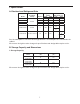
I. Specifications A. Electrical and Refrigerant Data Model CR1B-FG/FS/HS CF1B-FS/HS CR2B-FG/FS/HS CF2B-FS/HS AC Supply Voltage 115/60/1 Design Pressure (PSIG) Amperes HIGH LOW 4 240 120 9 450 250 7 240 120 11 450 250 CR3B-FS/HS 115/60/1 9 240 120 CF3B-FS/HS 208-230/115/60/1 16 450 250 Refrigerant (oz.) 134a 404A 11 8 12 17 1-Section 11 2-Section 12 1-Section 8 2-Section 17 See the nameplate for electrical and refrigerant data. The nameplate is located inside the cabinet.
2. Dimensions Dimensions Exterior Exterior Exterior Model Width (W) Height (H) Depth (D) Interior Width Interior Height Interior Depth One Section 698.5 (27.5) FG 579 (22.8) 884.9 (34.8) Two Section 1397 (55) 1920.5 1277.5 (50.3) 1513.6 (59.59) 711.2 (28) (75.61) FS/HS 1277.5 579 Three Section 2108.2 (83) 852.9 (33.58) (50.3) (22.8) Door Opening Width (DW) Model One Section 579 (22.8) Two Section 593.7 (23.37) Three Section 593.7 579 (23.37) (22.8) Door Opening Height (DH) 1513.6 (59.
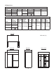
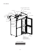
II. General Information A. Construction 1.
2.
3.
B. Sequence of Operation 1. Sequence Cycles and Shutdown The steps in the sequence are as outlined below. Note: 1. A float-switch controlled condensate pump (located on top of the appliance) is used to pump evaporator condensation to the condensate pan. 2. When exposed to high temperatures, a high-temperature alarm "Hi" may occur at start-up. To silence the alarm, press and release the upper button. Alarm automatically resets when temperature drops to an acceptable range. a) Refrigerator 1.
b) Freezer 1. Startup/Cool Down MH and PH energize. There is a slight delay before cabinet temperature appears on DM and Comp, ConFM, and EvapFM energize. 2. Cool Down Achieved CM monitors cooling of the cabinet via CTh. CTh cools to 3°F (1.7°C) below setpoint. EvapFM, MH, and PH continue. Comp and ConFM de-energize. 3. Cool Down Restart CTh warms to 3°F (1.7°C) above setpoint. EvapFM, MH, and PH continue. Comp and ConFM energize. 4. Defrost "dEF" is displayed during defrost.
CTh in control 2-min. Comp on timer starts 14 2-min. Comp off timer starts CTh cools to 3°F (1.7°C) below setpoint. Factory default 36°F (2°C) DTh in control DTh cools to 8.6°F (-13°C) EvapFM energized MH energized Comp de-energized ConFM de-energized CTh warms to 3°F (1.7°C) above setpoint 4. Defrost Comp energized ConFM energized EvapFM energized MH energized delay timer starts 2-min. temperature display DTh warms to 40°F (4.4°C) 5.
Comp energized ConFM energized EvapFM energized MH energized PH energized 2-min. Comp on timer starts Legend: Comp-compressor ConFM-condenser fan motor CTh-cabinet thermistor DH-defrost heater DTh-defrost thermistor EvapFM-evaporator fan motor MH-mullion heater PH-perimeter heater MH energized PH energized Power on Slight Delay at Startup CTh cools to 3°F (1.7°C) below setpoint.
C. Display Module When the power switch is moved to the "ON" position there is a slight delay, then the current cabinet temperature is displayed. From the display module, the cabinet setpoint and temperature display scale can be changed. For further details, see "II.C.2. Controls and Adjustments." Note: When exposed to high temperatures a high-temperature alarm "Hi" may occur at start‑up. To silence the alarm, press and release the upper button. Alarm clears once temperature is within factory parameters.
2. Controls and Adjustments a) Default Settings 1. Temperature Setting: Refrigerator: 36°F (2°C). Freezer: -4°F (-20°C). 2. Temperature Display Scale: F. b) Temperature Setpoint The temperature setpoint is the value for the average cabinet temperature. The temperature differential for the compressor to turn on and off is ±3°F (±1.7°C) of the temperature setpoint. For example, for a refrigerator temperature setpoint of 36°F (2°C), the compressor comes on at 39°F (3.
D. Control Module All models are pretested and factory set. NOTICE • The control module is fragile, handle very carefully. • Do not change wiring and connections. Never misconnect terminals. • Do not short out power supply to test for voltage. 1.
2. Alarm Safeties Alarm signals are designed to protect the appliance and food product. These alarms give information or warnings in the event the appliance is operating out of acceptable parameters. Should one of the alarms occur, follow the instructions in the table below to address the alarm. The alarm code flashes once every second with audible alarm. To silence the alarm, press and release the upper button.
E. Compressor Protector, Short Cycle Protection, and High-Pressure Switch 1. Compressor External or Internal Protector If combined temperature/amperage value is above the limit specified by the compressor manufacturer, the compressor external or internal protector operates independently to turn off the compressor. The compressor external or internal protector de-energizes the compressor until the temperature/amperage value returns to an acceptable level.
III. Technical Data A.
B. Wiring Diagrams 1.
2.
3.
4.
5.
6.
7. CR3B-FS/HS Receptacle Box Connection Note: Only the top receptacles have power. 8. CF3B-FS/HS Receptacle Box Connection Note: Only the top receptacles have power.
IV. Service Diagnosis WARNING • This appliance should be diagnosed and repaired only by qualified service personnel to reduce the risk of death, electric shock, serious injury, or fire. • Risk of electric shock. Use extreme caution and exercise safe electrical practices. • Moving parts (e.g., fan blade) can crush and cut. Keep hands clear. • Make sure all food zones are clean after the appliance is serviced. For cleaning procedures, see "VI.A. Cleaning Instructions." A.
1. Refrigerator 7) Startup/Cool Down–EvapFM and MH energize. There is a slight delay, then Comp and ConFM energize and cabinet temperature turns on. a) Startup Diagnosis: Check that EvapFM energizes. If not, confirm that the door(s) are closed and DS contacts are closed. Check EvapFM blades for binding. Next, check for 115VAC at DSR terminals 7 and 8. If 115VAC is not present, check DS continuity. If 115VAC is present, check DSR coil continuity and contact continuity between terminals 6 and 4.
8) Cool Down Achieved–CTh cools to 3°F (1.7°C) below setpoint. EvapFM and MH continue. Comp and ConFM de‑energize. Diagnosis: If Comp and ConFM do not deenergize, confirm CTh status. See "IV.C. Thermistor Check." If CTh ohm reading is in range and Comp and ConFM do not de-energize, replace CM. 9) Defrost Temperature-Initiated Defrost: DTh cools to 8.6°F (-13°C). EvapFM and MH continue. Comp and ConFM de-energize. Defrost Termination: DTh warms to 40°F (4.4°C). EvapFM and MH continue.
2. Freezer 7) Startup/Cool Down–MH and PH energize. There is a slight delay, then Comp, ConFM, and EvapFM energize and cabinet temperature appears on DM. Once DTh reaches 32°F (0°C), 4-hour Comp cumulative run timer starts. a) Startup Diagnosis: Check that EvapFM energize. If not, confirm that the door(s) are closed and DS contacts are closed. Check EvapFM blades for binding. Next, check for 115VAC at DSR terminals 7 and 8. If 115VAC is not present, check DS continuity.
• The appliance should be a minimum of 4" (11 cm) from side walls. • A minimum of 10" (25 cm) overhead clearance should be provided for proper ventilation. 8) Cool Down Achieved–CTh cools to 3°F (1.7°C) below setpoint. EvapFM, MH, and PH continue. Comp and ConFM de‑energize. Diagnosis: If Comp and ConFM do not de‑energize, confirm CTh status. See "IV.C. Thermistor Check." If CTh ohm reading is in proper range and Comp and ConFM do not de-energize, replace CM.
3-minute Comp delay timer terminates: Have Comp and ConFM energized after DH is de-energized for 3 minutes? If not, check for 115VAC between CM C1 and CM N5. If 115VAC is not present, replace CM. If 115VAC is present between CM C1 and CM N5, check for 115VAC on CR coil (terminals 5 and 6). If 115VAC is not present between CR 5 and CR 6, check continuity of HPS. If open, allow time for HPS to reset. If HPS does not reset, replace HPS and diagnose reason for HPS activation. See "IV.A.2.7)c) HPS Activation.
B. Control Module Check Before replacing a control module that does not show a visible defect and that you suspect is bad, always conduct the following check procedure. This procedure will help you verify your diagnosis. Always choose a neutral (W wire) to establish a good neutral connection when checking high voltages. Also, confirm that there is a good neutral connection to the control module terminal N5. Alarm Reset: To silence the alarm, press and release the upper or lower button with power on.
C. Thermistor Check In the event the cabinet thermistor reading is out of range (E1 alarm), the compressor operates on a fixed time basis of 5-minutes on and 5-minutes off. In the event the refrigerator defrost thermistor reading is out of range (E2 alarm), defrost initiation occurs every 4-hours of cumulative compressor run time and terminates on 20-minute minimum defrost timer.
D. Diagnostic Chart Before consulting the diagnostic charts, check the following: • Check the setpoint. For factory default settings, see "II.C.2.a) Default Settings." • Make sure the doors are not left open or opened too often and that they are sealing properly. • Make sure product is not blocking airflow or that the cabinet is not overloaded with warm or hot product. Product should be cooled before putting it in the appliance. • Check for correct installation and proper voltage per appliance nameplate.
Appliance Not Cooling - Possible Cause 11. Compressor Protector a) Dirty condenser. b) Condenser fan not operating. c) Defective. 12. Compressor a) Defective. 13. Condenser a) Dirty. 14. Evaporator See "2. Evaporator is Frozen Up." 15. Refrigerant/Refrigerant Lines a) Clogged or frozen. a) Gas leak. b) Refrigerant lines restricted. 2. Evaporator is Frozen Up Evaporator is Frozen Up - Possible Cause 1. Evaporator a) Dirty. 2. Evaporator Fan a) Not operating. 3.
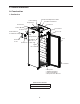
V. Replacement of Components WARNING • This appliance should be diagnosed and repaired only by qualified service personnel to reduce the risk of death, electric shock, serious injury, or fire. • Move the power switch to the "OFF" position, then unplug the appliance from the electrical outlet before servicing. • Make sure all food zones in the appliance are clean after the appliance is serviced. For cleaning procedures, see "VI.A. Cleaning Instructions." A.
2. Brazing WARNING • R-134a and R-404A themselves are not flammable at atmospheric pressure and temperatures up to 176°F (80°C). • R-134a and R-404A themselves are not explosive or poisonous. However, when exposed to high temperatures (open flames), R-134a and R-404A can be decomposed to form hydrofluoric acid and carbonyl fluoride both of which are hazardous. • Do not use silver alloy or copper alloy containing arsenic. • Use an electronic leak detector or soap bubbles to check for leaks.
5) Disconnect the gauge manifold hose from the vacuum pump and attach it to a refrigerant service cylinder. Remember to loosen the connection and purge the air from the hose. See the nameplate for the required refrigerant charge. Hoshizaki recommends only virgin refrigerant or reclaimed refrigerant which meets ARI Standard 700 (latest edition) be used. 6) A liquid charge is required when charging an R-404A system (to prevent fractionation) and optional when charging an R-134a system.
B. Important Notes for Component Replacement NOTICE When replacing a component listed below, see the notes to help ensure proper operation. Component Notes Compressor Install a new start relay, start capacitor, and compressor protector (compressor protector is integrated with the start relay on refrigerators; internal on 1-section freezers; external on 2-section freezers).
VI. Maintenance A. Cleaning Instructions WARNING • Before cleaning the appliance, move the power switch to the "OFF" position and unplug the appliance to prevent electric shock by unexpected entrance of water into the appliance or injury by moving parts. • Before cleaning the appliance, move all foods into another clean refrigerator or freezer. • Do not splash water directly onto the appliance. This might cause short circuit, electric shock, corrosion, or failure.
B. Maintenance 1. Condenser Check the condenser once a year and use a brush or vacuum cleaner to clean the condenser as required. 2. Power Supply Connection If a plug, power cord, or receptacle (three-section models) is damaged, replace it. Be sure to connect the ground wire. C. Preparing the Appliance for Periods of Non-Use WARNING • When preparing the appliance for long storage, prevent the doors from closing to reduce the risk of children getting trapped.
VII. Disposal WARNING When preparing the appliance for disposal, remove the door to reduce the risk of children getting trapped. Leave the shelves in place so that children may not easily climb inside. This appliance contains refrigerant and must be disposed of in accordance with applicable national, state, and local codes and regulations. Refrigerant must be recovered by properly certified service personnel.