Hoshizaki Hoshizaki America, Inc. Cubelet Icemaker/Dispenser Models DCM-270BAH(-OS) “A Superior Degree of Reliability” SERVICE MANUAL www.hoshizaki.
IMPORTANT Only qualified service technicians should attempt to service or maintain this ice dispenser. No service or maintenance should be undertaken until the technician has thoroughly read this service manual. HOSHIZAKI provides this manual primarily to assist qualified service technicians in the service and maintenance of the dispenser.
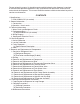
Please review this manual. It should be read carefully before the ice dispenser is serviced or maintenance operations performed. Only qualified service technicians should service and maintain the dispenser. This manual should be made available to the technician prior to service or maintenance. CONTENTS I. Specifications .................................................................................................................... 4 1. DCM-270BAH-OS (air-cooled) ........................................
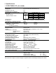
I. Specifications 1. DCM-270BAH-OS (air-cooled) AC SUPPLY VOLTAGE AMPERAGE MAXIMUM FUSE SIZE MINIMUM CIRCUIT AMPACITY APPROXIMATE ICE PRODUCTION PER 24 HR. lbs./day ( kg/day ) Reference without *marks SHAPE OF ICE ICE QUALITY APPROXIMATE STORAGE CAPACITY ELECTRIC & WATER CONSUMPTION ELECTRIC W (kWH/100 lbs.) POTABLE WATER gal./24HR (gal./100 lbs.
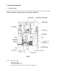
II. General Information 1. Construction The Hoshizaki Cubelet Ice Dispenser, model DCM-270BAH-OS includes water supply, freezer, condensing, storage, dispensing and control assemblies. Fig. 1 Note: *Adjustable Legs Minimum height - 4" Maximum height - 5.3" Do not adjust exceeding the above recommendation.
2.Operation - How it works Water flows from the potable water source through the water supply line shut-off valve, enters at the water inlet fitting and into the water reservoir. The water reservoir functions to maintain a constant water level inside the freezer assembly. Water from the water reservoir enters at the bottom of the freezer. Heat is removed by the refrigeration process and ice forms inside the freezer.
III. Technical Information 1.
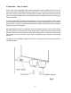
2. Performance Data [a] DCM-270BAH-OS (air-cooled) Note: Pressure data is recorded first 5 minutes in freezing cycle. The data without *marks should be used for reference. We reserve the right to make changes in specifications and design without prior notice.
3.
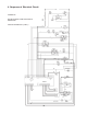
4. Sequence of Electrical Circuit POWER ON WATER STARTS TO BE SUPPLIED TO RESERVOIR AGITATION TIMER ON - (2 SEC.
RESERVOIR FILLS UP GEAR MOTOR TURNS ON 11
COMPRESSOR STARTS 60 SEC. AFTER GEAR MOTOR.
ICE MAKING CONTINUES.
BIN CONTROL TRIPS. COMPRESSOR STOPS 90 SECONDS LATER.
GEAR MOTOR STOPS 60 SECONDS AFTER COMPRESSOR.
DISPENSE ICE (BIN CONTROL STILL TRIPPED) 16
FLUSH SWITCH ACTIVATED.
FLUSH TIMER ACTIVATED.
AGITATION TIMER ACTIVATES GEAR MOTOR.
IV. Service Diagnosis 1. No Ice Production PROBLEM [1] The ice dispenser will not start. POSSIBLE CAUSE a) Power Supply Cord b) Power Switch (on left bottom of front panel) c) Fuse 1A (Control Box) [2] Water valve operates, a) Water Supply Line but no ice is produced. b) Water Valve c) Water Control Relay [3] Compressor will not start. 4. Blown fuse. 1. OFF position. 1. Blown out. 1. Shut-off valve closed. 2. Water supply off. 1. Clogged. 1. Bad contacts (terminal nos. 4 and 6). d) Timer 2.
PROBLEM POSSIBLE CAUSE [5] Fan motor will not start. a) Fan Motor b) Timer REMEDY 1. Motor winding opened. 1. Replace. 2. Bearing worn out. 2. Replace. 3. Wiring to fan motor. 3. Check for loose connection or open, and replace. 4. Fan blade bound. 4. Check and replace. 1. Bad contacts (X2 relay). 1. Check for continuity and replace. 2. X2 relay coil winding opened. [6] No water or poor flow. a) Water Supply 3. Loose connections. 1. Water failure or pressure too low. 2.
2. Low Ice Production PROBLEM POSSIBLE CAUSE [1] Abnormal refrigeration a) Condenser circuit. 1. Dirty air filter or condenser. 2. Bad ventilation. REMEDY 1. Clean. 2. Remove anything blocking vents. b) Thermostatic Expansion 1. Low-side pressure or 1. Secure bulb to low-side line Valve temperature exceeding or replace. the limit. c) Refrigerant Lines 1. Gas leaks. 1. Check for leaks with a leak detector. Reweld leak, replace drier and charge with refrigerant.
3. Faulty Dispenser PROBLEM [1] No ice is dispensed. POSSIBLE CAUSE a) Storage Bin 1. Ice block or bridge. 2. Incorrect wiring. 1. Deformed due to ice block or bridge. c) Solenoid 1. Coil winding opened. d) Ice switch or dispensing 1. Bad contacts. sensor. e) Ice Dispensing Relay 1. Bad contacts. b) Agitator [2] No water is dispensed. a) Water Valve (Dispensing) b) Water Dispensing Sensor [3] Ice keeps being a) Shutter dispensed. b) Ice Switch Dispensing Switch 1. Clogged filter. 1. Bad circuit. 1.
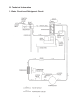
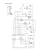
If you experience problems with the ice or water dispense, use the following charts along with the wiring diagram (section III, 3) to guide you through your troubleshooting. The following tables show the proper voltage readings for each operation.
4. Other PROBLEM [1] Ice dispenser will not stop even if filled with ice. [2] Reservoir overflows (water will not stop). POSSIBLE CAUSE a) Bin Control Switch b) Water Control Relay c) Timer a) Water Supply 1. 2. 1. 1. 1. Contacts fused. Out of position. Contacts fused. Defective. Water pressure too high. b) Water Valve c) Float Switch d) [3] A lot of water drains from gear motor drain pipe. [4] Abnormal noise. a) a) b) c) d) 1. Cannot close. 1. Bad contacts (red and black leads). 2. Defective.
V. Removal and Replacement of Components IMPORTANT Ensure all components, fasteners and thumbscrews are securely in place after the equipment is serviced. IMPORTANT 1. The Polyol Ester (POE) oils used in R-404A units can absorb moisture quickly. Therefore it is important to prevent moisture from entering the system when replacing or servicing parts. 2. Always install a new filter drier every time the sealed refrigeration system is opened. 3.
4) Close the low-side valve and high-side valve on the service manifold. 5) Disconnect the vacuum pump, and attach a refrigerant service cylinder to the high-side line. Remember to loosen the connection, and purge the air from the hose. See the nameplate for the required refrigerant charge. Hoshizaki recommends only virgin refrigerant or reclaimed refrigerant which meets ARI Standard No. 700-88 be used. 6) A liquid charge is recommended for charging an R-404A system. Invert the service cylinder.
3. Removal and Replacement of Compressor IMPORTANT Always install a new drier every time the sealed refrigeration system is opened. Do not replace the drier until after all other repair or replacement has been made. Note: When replacing a compressor with a defective winding, be sure to install the new start capacitor and start relay supplied with the replacement compressor.
12) Braze the process, suction and discharge lines (do not change this order), while purging with nitrogen gas flowing at the pressure 3-4 PSIG. 13) Install the new filter drier. 14) Check for leaks using nitrogen gas (140 PSIG) and soap bubbles. 15) Connect the terminals, and replace the terminal cover in its correct position. 16) Evacuate the system, and charge it with refrigerant. See the nameplate for the required refrigerant charge. 17) Replace the panels in their correct positions.
5. Removal and Replacement of Thermostatic Expansion Valve IMPORTANT Sometimes moisture in the refrigerant circuit exceeds the drier capacity and freezes up at the expansion valve. Always install a new drier every time the sealed refrigeration system is opened. Do not replace the drier until after all other repair or replacement has been made. 1) Turn off the power supply, and unplug the dispenser. 2) Remove the panels. 3) Recover the refrigerant and store it in an approved container.
14) Place the new expansion valve cover in position. 15) Replace the panels in their correct positions. 16) Plug in the dispenser and turn on the power supply. 6. Removal and Replacement of Pressure Switch IMPORTANT Always install a new drier every time the sealed refrigeration system is opened. Do not replace the drier until after all other repair or replacement has been made. 1) Turn off the power supply and unplug the dispenser. 2) Remove the panels.
7. Removal and Replacement of Control Water Valve 1) Unplug the icemaker. 2) Remove the panels. 3) Close the water supply line shut-off valve. 4) Disconnect the terminal from the control water valve. 5) Loosen the fitting nut on the control water valve inlets, and remove the control water valve. Do not lose the packings inside the fitting nut. 6) Remove the water supply hose from the control water valve. 7) Install the new control water valve.
8. Removal and Replacement of Flush Water Valve 1) Turn off the power supply. 2) Remove the panels. 3) Close the water supply line shut-off valve. 4) Remove the clamp and disconnect the hose from the flush water valve that attaches to the evaporator. Note: Water may still remain inside the evaporator. Be sure to drain the water into the drain pan. 5) Disconnect the flush water valve from the tube connected to the plastic tee leading to the drain hose. 6) Disconnect the terminals from the flush water valve.
9. Removal and Replacement of Float Switch WARNING 1. Fragile, handle very carefully. 2. If the float switch works poorly because of scale or other foreign matter, install a filter or softener in the water supply line. 1) Unplug the dispenser and turn off the power supply. 2) Close the water supply line shut-off valve. 3) Remove the panels. 4) Flush water out of the system. 5) Cut the float switch leads at the wire connectors. 6) Turn and unfasten the flanged top, and remove the float switch.
10. Removal and Replacement of Bin Control Switch Assembly 1) Turn off the power supply and unplug the dispenser. 2) Remove the top panel. 3) Remove the bin control switch from the storage bin cover. (Twist, then pull up.) 4) Cut the wire leads and remove switch. 5) Assemble the replacement switch, reversing the procedure used to remove the old switch. 6) Plug in the dispenser, turn on the power supply and check that the bin control switch works normally.
11. Removal and Replacement of Storage Bin Assembly 1) Move the ice making switch to the “FLUSH” position. 2) Press the push button to dispense ice and remove all ice from the storage bin. 3) Turn off the power supply and unplug the dispenser. 4) Remove the panels. 5) Remove the storage bin cover. 6) Remove the agitator, drip ring, drip plate and shutter assembly. 7) Remove the three socket head cap screws and lift off the storage bin assembly. 8) Install the new storage bin assembly.
12. Removal and Replacement of Agitator and Drip Ring 1) Move the ice making switch to the “OFF” position. 2) Press the push button to dispense ice and remove all ice from the storage bin. 3) Turn off the power supply, and unplug the dispenser. 4) Remove the top panel. 5) Remove the storage bin cover. 6) Rotate the agitator counterclockwise and lift off. 7) Rotate the drip ring about 30 degrees clockwise and lift off. 8) Install the new drip ring and agitator.
13. Removal and Replacement of Evaporator Assembly 1) Move the ice making switch to the “OFF” position. 2) Press the push button to dispense ice and remove all ice from the storage bin. 3) Turn off the power supply, and unplug the dispenser. 4) Flush all water out of the system. 5) Remove the panels. 6) Remove the storage bin assembly. (See “11. Removal and Replacement of Storage Bin Assembly.”) Extruding Head 7) Lift off the extruding head.
13) Disconnect the brazing-connections of the expansion valve and the copper tube - low side from the evaporator, using brazing equipment. 14) Braze the new evaporator with nitrogen gas flowing at a pressure of 3-4 PSIG. 15) Replace the drier. 16) Check for leaks using nitrogen gas (140 PSIG) and soap bubbles. 17) Evacuate the system and charge it with refrigerant. See the nameplate for the required refrigerant charge. 18) Remove the four socket head cap screws at the bottom of the evaporator.
28) Assemble the removed parts in the reverse order of which they were removed WARNING Be careful not to scratch the surface of the O-ring, or it may cause water leaks. Handle the mechanical seal with care not to scratch nor to contaminate its contact surface. 29) Check for water leaks. WARNING After assembling the extruding head, be sure to check that the auger does not come into contact with the inner surface of the evaporator and that there is not any abnormal noise from the bearing.
VI. Cleaning and Maintenance Instructions IMPORTANT Ensure all components, fasteners and thumbscrews are securely in place after any maintenance or cleaning is done to the equipment. 1. Preparing the Ice Dispenser for Long Storage IMPORTANT When shutting off the ice dispenser for an extended time, drain out all water from the water line and remove the ice from the storage bin. The storage bin should be cleaned and dried.
2. Cleaning Instructions WARNING 1. HOSHIZAKI recommends cleaning this unit at least twice a year. More frequent cleaning, however, may be required in some existing water conditions. 2. To prevent injury to individuals and damage to the ice dispenser, do not use ammonia type cleaners. 3. Always wear liquid-proof gloves for safe handling of the cleaning and sanitizing solutions. This will prevent irritation in case the solution contacts the skin.
Fig. 4 Fig.
12) Replace the drip ring and agitator. 13) Move the ice making switch and then the power switch to the “ON” position. Place the storage bin cover in position, and start the automatic icemaking process. Run the ice dispenser until it stops automatically. 14) Move the ice making switch to the “FLUSH” position, and wait for flush process to begin (60 seconds).
[b] Sanitizing Procedure 1) Dilute approximately 1.5 fl. oz. of a 5.25% sodium hypochlorite solution (chlorine bleach) with 3 gal. of water. 2) Pour the sanitizing solution carefully into the reservoir through the opening in the center of the storage bin up to an overflow level. 3) Wait for 10 minutes to start the icemaking process. Move the ice making switch to the “ON” position, and start the automatic icemaking process. Run the ice dispenser until it stops automatically.
2. Maintenance Instructions IMPORTANT This ice dispenser must be maintained individually, referring to the instruction manual and labels provided with the ice dispenser. 1) Stainless Steel Exterior To prevent corrosion, wipe the exterior occasionally with a clean and soft cloth. Use a damp cloth containing a neutral cleaner to wipe off oil or dirt build up. 2) Air Filter - See Fig. 6 A plastic mesh air filter removes dirt or dust from the air, and keeps the condenser from getting clogged.