Hoshizaki Hoshizaki America, Inc. Modular Flaker Models FD-1001MAH(-C) FD-1001MWH(-C) FD-1001MRH(-C) FD-1001MLH(-C) “A Superior Degree of Reliability” INSTRUCTION MANUAL www.hoshizaki.
IMPORTANT Only qualified service technicians should install, service, and maintain the icemaker. No installation, service, or maintenance should be undertaken until the technician has thoroughly read this Instruction Manual. Likewise, the owner/manager should not proceed to operate the icemaker until the installer has instructed them on its proper operation.
IMPORTANT This manual should be read carefully before the icemaker is installed and operated. Only qualified service technicians should install, service, and maintain the icemaker. Read the warnings contained in this booklet carefully as they give important information regarding safety. Please retain this booklet for any further reference that may be necessary. CONTENTS Important Safety Information.................................................................................................. 5 I.
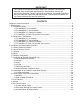
III. Cleaning and Maintenance.............................................................................................. 36 A. Cleaning and Sanitizing Instructions............................................................................ 36 1. Cleaning Solution................................................................................................... 36 2. Cleaning Procedure................................................................................................ 36 3.
Important Safety Information Throughout this manual, notices appear to bring your attention to situations which could result in death, serious injury, or damage to the unit. WARNING Indicates a hazardous situation which could result in death or serious injury. CAUTION Indicates a situation which could result in damage to the unit. IMPORTANT Indicates important information about the use and care of the unit.
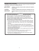
I. Specifications A. Nameplate Rating 1. FD-1001MAH(-C) (air-cooled) HOSHIZAKI ICE MAKER MODEL NUMBER SERIAL NUMBER AC SUPPLY VOLTAGE FD-1001MAH COMPRESSOR GEAR MOTOR FAN MOTOR OTHER MAXIMUM FUSE SIZE MAX HACR BREAKER (USA ONLY) MAX CIRC BREAKER (CANADA ONLY) MINIMUM CIRCUIT AMPACITY DESIGN PRESSURE REFRIGERANT 208-230/60/1 (3 WIRE WITH NEUTRAL FOR 115V) 240V 4.2RLA 34LRA 120V 3.0FLA 1/4HP 115V 0.85FLA 1/15HP 120V 0.03A 15 AMPS 15 AMPS 15 AMPS 15 AMPS HI-427PSI LO-230PSI 404A 1 LB 12 OZ.
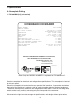
2. FD-1001MWH(-C) (water-cooled) HOSHIZAKI ICE MAKER MODEL NUMBER SERIAL NUMBER AC SUPPLY VOLTAGE FD-1001MWH COMPRESSOR GEAR MOTOR FAN MOTOR OTHER MAXIMUM FUSE SIZE MAX HACR BREAKER (USA ONLY) MAX CIRC BREAKER (CANADA ONLY) MINIMUM CIRCUIT AMPACITY DESIGN PRESSURE REFRIGERANT 208-230/60/1 (3 WIRE WITH NEUTRAL FOR 115V) 240V 4.2RLA 34LRA 120V 3.0FLA 1/4HP --- --- --120V 0.03A 15 AMPS 15 AMPS 15 AMPS 15 AMPS HI-427PSI LO-230PSI 404A 1 LB 1 OZ.
3. FD-1001MRH(-C) (remote air-cooled) HOSHIZAKI ICE MAKER MODEL NUMBER SERIAL NUMBER AC SUPPLY VOLTAGE FD-1001MRH COMPRESSOR GEAR MOTOR FAN MOTOR OTHER MAXIMUM FUSE SIZE MAX HACR BREAKER (USA ONLY) MAX CIRC BREAKER (CANADA ONLY) MINIMUM CIRCUIT AMPACITY DESIGN PRESSURE REFRIGERANT 208-230/60/1 (3 WIRE WITH NEUTRAL FOR 115V) 240V 4.2RLA 34LRA 120V 3.0FLA 1/4HP REMOTE 120V 3A MAX 120V 0.
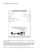
4. FD-1001MLH(-C) (low-side, parallel rack system) HOSHIZAKI ICE MAKER MODEL NUMBER SERIAL NUMBER AC SUPPLY VOLTAGE COMPRESSOR GEAR MOTOR FAN MOTOR OTHER MAXIMUM FUSE SIZE MAX. HACR BREAKER (USA ONLY) MAX. CIRC. BREAKER (CANADA ONLY) MINIMUM CIRCUIT AMPACITY DESIGN PRESSURE REFRIGERANT FD-1001MLH 115-120/60/1 --- --- --120V 3.0FLA 1/4HP --- --- --120V 0.53A 15 AMPS 15 AMPS 15 AMPS 15 AMPS HI-427PSI LO-230PSI 404A MOTOR-COMPRESSOR THERMALLY PROTECTED, NOT INTENDED FOR OUTDOOR USE! Hoshizaki America, Inc.
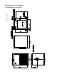
B. Dimensions / Connections Unit = mm [in.] 1.
Unit = mm [in.] 2.
Unit = mm [in.] 3.
Unit = mm [in.] 4.
II. Installation and Operating Instructions WARNING 1. This icemaker must be installed in accordance with all applicable national, state, and local regulations. 2. CHOKING HAZARD: Ensure all components, fasteners, and thumbscrews are securely in place after installation. Make sure that none have fallen into the dispenser unit/storage bin. A. Checks Before Installation • Visually inspect the exterior of the shipping container and immediately report any damage to the carrier.
C. Location CAUTION 1. This icemaker is not intended for outdoor use. Normal operating ambient temperature should be within 45°F to 100°F (7°C to 38°C); Normal operating water temperature should be within 45°F to 90°F (7°C to 32°C). Operation of the icemaker, for extended periods, outside of these normal temperature ranges may affect icemaker performance. 2. This icemaker will not work at sub-freezing temperatures.
E. Electrical Connection WARNING For All Models 1. Electrical connection must be hard-wired and must meet national, state, and local electrical code requirements. Failure to meet these code requirements could result in death, electric shock, serious injury, fire, or severe damage to equipment. 2. This unit requires an independent power supply. See the nameplate for proper voltage and breaker/fuse size.
F. Installation of Remote Condenser Unit WARNING 1. Installation of remote condenser unit must be performed by properly trained and EPA-certified service personnel. 2. Failure to install the equipment within these guidelines may adversely affect safety, performance, component life, and warranty coverage. 1. Checks Before Installation 1) Remove the shipping carton, tape, and packing material. 2) Check that the refrigerant lines do not rub or touch lines or other surfaces, and that the fan blade moves freely.
3. Setup Bolts with Split Lock Washer and Flat Washer 1) Secure the legs to the remote condenser unit with the 8 bolts and nuts provided. See Fig. 5. 2) The legs have 8 mounting holes. Secure the legs with 8 bolts (not included). Nuts Fig. 5 4. Line Set CAUTION The icemaker, line set, and remote condenser unit must contain the same type of refrigerant. Mixing of refrigerants will result in improper operation and possible damage to the refrigeration system.
2) Connect the refrigerant lines to the appropriate male fittings on the remote condenser unit first and then at the icemaker. Make a proper connection as follows: a. Remove the protective covers from the male fitting and female coupling. b. Apply Polyol Ester (POE) refrigerant oil to the entire male fitting, including threads, o‑ring, and diaphragm, before making the connection. See Fig. 7. CAUTION Do not use thread sealant on the fittings. Use POE refrigerant oil only. c.
c. Make sure the male fitting and female coupling are properly aligned, then start the connection by hand to ensure that it is not cross threaded. d. Place a backup wrench on the back of the female coupling, then tighten the connection with a wrench until it is tight. At this point, the nut has covered most of the threads on the male fitting. CAUTION! Failure to use a backup wrench may result in damage to the line set and possible refrigerant leaks. e.
5. Electrical Connection WARNING 1. Electrical connection must meet national, state, and local electrical code requirements. Failure to meet these code requirements could result in death, electric shock, serious injury, fire, or severe damage to equipment. 2. THE REMOTE CONDENSER UNIT MUST BE GROUNDED. Install a proper ground wire from the icemaker to the remote condenser unit. Use wire of an appropriate gage and outdoor rating. Failure to properly ground the unit could result in death or serious injury.
6. Stacking Remote Condenser Units 1) Install the lower remote condenser unit as described earlier in this section. 2) Place the upper remote condenser unit on top of the lower. See Fig. 10. 3) Secure the upper remote condenser unit to the lower remote condenser unit with the 4 screws provided. 4) Install refrigerant lines and make electrical connection as described earlier in this section. Upper Remote Condenser Unit Screws Screws Lower Remote Condenser Unit Fig.
G. Connection to an R-404A Parallel Rack System WARNING 1. Installation must be performed by properly trained and EPA-certified service personnel. 2. Failure to install the equipment within these guidelines may adversely affect safety, performance, component life, and warranty coverage. 3. The icemaker, line set, and rack system must contain the same type of refrigerant. Mixing of refrigerants will result in improper operation and possible damage to the refrigeration system.
7) Connect the refrigerant lines to the appropriate fittings on the rack system first (if not already brazed on), then at the icemaker. If the couplings to the rack system are not Parker quick connect couplings, follow the coupling manufacturer's instructions. Make a proper Parker quick connect coupling connection as follows: a. Remove the protective covers from the male fitting and female coupling. b.
Male Fitting DO NOT USE THREAD SEALANT Brush Threads Diaphragm Apply POE Oil to Entire Male Fitting O-Ring POLYOL ESTER (POE) OIL THREAD SEALANT Fig. 12 Reference Line Wrench 1/6 Turn After Tight, Tighten an Additional 1/6 Turn Backup Wrench Backup Wrench Fig.
H. Water Supply and Drain Connections See Fig. 14, 15, or 16 WARNING 1. Water supply and drain connections must be installed in accordance with applicable national, state, and local regulations. 2. Normal operating water temperature should be within 45°F to 90°F (7°C to 32°C). Operation of the icemaker, for extended periods, outside of this normal temperature range may affect icemaker performance. 3.
1. Icemaker • If you would like to convert to top water supply, install the optional Top Water Supply Kit (HS-2123). • Icemaker water supply inlet is 1/2" female pipe thread (FPT). A minimum of 3/8" OD copper tubing is recommended for the icemaker water supply line. • An icemaker water supply line shut-off valve and drain valve should be installed. • Icemaker drain outlet is 3/4" FPT. A minimum of 3/4" OD hard pipe is recommended for the icemaker drain line.
2. Water-Cooled Condenser a) Connection to an Open Drain System • Condenser water supply inlet is 1/2" female pipe thread (FPT). A minimum of 3/8" OD copper tubing is recommended for the condenser water supply line. • A condenser water supply line shut-off valve and drain valve should be installed. • Condenser drain outlet is 3/8" FPT. A minimum of 3/8" OD hard pipe is recommended for the condenser drain line. • In some areas, a back flow preventer may be required in the cooling water circuit.
b) Connection to a Closed Loop System • Condenser water supply inlet is 1/2" female pipe thread (FPT). A minimum of 3/8" OD copper tubing is recommended for the condenser water supply line. • Condenser return outlet is 3/8" FPT. A minimum of 3/8" OD hard pipe is recommended for the condenser return line. • Shut-off valves and drain valves should be installed at both the condenser water supply inlet and condenser return outlet. • The water supply to the condenser should not drop below 4 GPM.
I. Final Checklist WARNING CHOKING HAZARD: Ensure all components, fasteners, and thumbscrews are securely in place after installation. Make sure that none have fallen into the storage bin.
J. Startup WARNING 1. All parts are factory-adjusted. Improper adjustments may adversely affect safety, performance, component life, and warranty coverage. 2. If the icemaker is turned off, wait for at least 3 minutes before restarting the icemaker to prevent damage to the compressor. 3. At startup, confirm that all internal and external connections are free of leaks. 4. On remote air-cooled model, the icemaker should have power for a minimum of 4 hours prior to startup to prevent compressor damage.
K. Bin Control Check An infrared sensor is used as the primary bin control to control the level of ice in the dispensing unit/storage bin. A mechanical bin control is used as a backup bin control. IMPORTANT 1. Make sure the icemaker has been installed as outlined in this manual and that the water supply is on. 2. Make sure S1 Dip Switch 7 is in the "ON" position. This allows the control board to monitor the infrared sensor along with the mechanical backup bin control. 1.
7) "GM" LED and "COMP" LED are on. Use an object to cover the infrared sensor lens at the bottom of the icemaker. If the bottom of the icemaker is not accessible in your application, remove the thumbscrew securing the infrared sensor housing, remove the housing from the base, then cover the infrared sensor lens. See Fig. 18. The yellow LED on the infrared sensor turns on. The yellow LED flashes when ice is at the outer limit of its range and turns steady as ice nears.
2. Mechanical Backup Bin Control Check 1) Make sure the power supply is off. 2) Remove the strap connecting the spout to the chute assembly. See Fig. 19. Pull up the chute assembly slightly so that you can access the actuator located in the top of the chute. 3) Move the power switch to the "ON" position. 4) Turn on the power supply to start the automatic icemaking process. Strap Proximity Switch Actuator Spout Chute Assembly Strap Fig. 19 5) Make sure the "GM" LED is on. See Fig. 14.
3. Infrared Sensor Shutdown Delay This is the delay between the infrared sensor detecting ice and the start of the shutdown sequence. The infrared sensor shutdown delay is factory-adjusted to 100 seconds and no adjustment is required for most dispenser unit/storage bin applications. a) Standard Storage Bin: When installed on a standard storage bin, any shutdown delay setting is acceptable. b) Dispenser Unit: For typical dispenser unit applications, a 100-second shutdown delay is recommended.
III. Cleaning and Maintenance WARNING CHOKING HAZARD: Ensure all components, fasteners, and thumbscrews are securely in place after any cleaning or maintenance is done to the unit. Make sure that none have fallen into the dispenser unit/storage bin. A. Cleaning and Sanitizing Instructions Hoshizaki recommends cleaning and sanitizing this unit at least twice a year. More frequent cleaning and sanitizing, however, may be required in some existing water conditions. WARNING 1.
6) Remove the strap connecting the spout to the chute assembly, then remove the spout. See Fig. 20. 7) Pour the cleaning solution over the extruding head until the evaporator assembly and the reservoir are full and the solution starts to overflow into the drain pan. Note: If there is excess scale on the extruding head, fill the evaporator assembly and reservoir as described above, then use a clamp on the reservoir hose between the reservoir and evaporator assembly to block flow.
11) Wipe down the infrared sensor's lens, (located on the bottom of the icemaker) with the cleaning solution. See Fig. 22. Next, rinse the cleaning solution off of the infrared sensor's lens with a clean, damp cloth. Infrared Sensor Infrared Sensor Housing Fig. 22 Lens 12) Move the control switch to the "ICE" position, then move the power switch to the "ON" position. Replace the panels in their correct positions.
3. Sanitizing Solution IMPORTANT For safety and maximum effectiveness, use the solution immediately after dilution. Dilute 2.5 fl. oz. (74 ml or 5 tbs) of a 5.25% sodium hypochlorite solution (chlorine bleach) with 5 gal. (19 l) of warm water. 4. Sanitizing Procedure - Initial 1) Make sure the power supply is off and the water supply line shut-off valve is closed. Remove the panels, then move the power switch to the "OFF" position.
14) Turn on the power supply and allow the solution to drain for 5 minutes. 15) Turn off the power supply. 5. Sanitizing Procedure - Final 1) Mix a new batch of the sanitizing solution. 2) Make sure the power supply is off and the water supply line shut-off valve is closed. Remove the front and top panels, then move the power switch to the "OFF" position. 3) Remove the strap connecting the spout to the chute assembly, then remove the spout.
B. Maintenance This icemaker must be maintained individually, referring to the instruction manual and labels provided with the icemaker. The schedule below is a guideline. More frequent maintenance, however, may be required depending on water quality, the icemaker's environment, and local sanitation regulations. Consult with your local distributor about inspection and maintenance service. To obtain the name and phone number of your local distributor, visit www.hoshizaki.
Frequency After 3 Years, then Yearly Area Upper Bearing (extruding head); Lower Bearing and O-Ring (lower housing); Mechanical Seal; Evaporator Cylinder; Auger Maintenance Schedule (continued) Task Inspect. Replace both upper bearing and lower bearing if wear exceeds factory recommendations. Replace the mechanical seal if the seal's contact surfaces are worn, cracked, or scratched. C.
6) Turn on the power supply, then move the power switch to the "ON" position. Blow out the evaporator drain line using the compressed air or carbon dioxide supply until water stops coming out. 7) Move the power switch to the "OFF" position, then turn off the power supply. Reconnect the evaporator drain line hose. 8) Replace the front panel in its correct position. 9) Remove all ice from the dispenser unit/storage bin. Clean the dispenser unit/storage bin liner using a neutral cleaner.
HOSHIZAKI AMERICA, INC. 618 Hwy. 74 S., Peachtree City, GA 30269 USA TEL (770) 487-2331 FAX (770) 487-3360 www.hoshizaki.