Hoshizaki Hoshizaki America, Inc. Modular Crescent Cuber Models KM-650MAH KM-650MWH KM-650MRH “A Superior Degree of Reliability” INSTRUCTION MANUAL www.hoshizaki.
IMPORTANT Only qualified service technicians should install, service, or maintain this icemaker. No installation, service, or maintenance should be undertaken until the technician has thoroughly read this Instruction Manual. Likewise, the owner/manager should not proceed to operate the icemaker until the installer has instructed them on its proper operation.
IMPORTANT This manual should be read carefully before the icemaker is installed and operated. Only qualified service technicians should install, service, and maintain the icemaker. Read the warnings contained in this booklet carefully as they give important information regarding safety. Please retain this booklet for any further reference that may be necessary. CONTENTS Important Safety Information.................................................................................................. 4 I.
Important Safety Information Throughout this manual, notices appear to bring your attention to situations which could result in death, serious injury, or damage to the unit. WARNING Indicates a hazardous situation which could result in death or serious injury. CAUTION Indicates a situation which could result in damage to the unit. IMPORTANT Indicates important information about the use and care of the unit.
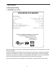
I. Specifications A. Nameplate Rating 1. KM-650MAH (air-cooled) HOSHIZAKI ICE MAKER MODEL NUMBER SERIAL NUMBER AC SUPPLY VOLTAGE KM-650MAH 208-230/60/1(3 WIRE WITH NEUTRAL FOR 115V) COMPRESSOR 208-230V 6.0RLA 40LRA PUMP 120V 0.5FLA 10W FAN 120V 1.0FLA 30W OTHER 115-120V 0.15A MAXIMUM FUSE SIZE 15 AMPS MAX. HACR BREAKER(USA ONLY) 15 AMPS MAX. CIRC. BREAKER (CANADA ONLY) 15 AMPS MINIMUM CIRCUIT AMPACITY 15 AMPS DESIGN PRESSURE HI - 467PSI LO - 230PSI REFRIGERANT 404A 1 LB. 8.7 OZ.
2. KM-650MWH (water-cooled) HOSHIZAKI ICE MAKER MODEL NUMBER SERIAL NUMBER AC SUPPLY VOLTAGE KM-650MWH 208-230/60/1 (3 WIRE WITH NEUTRAL FOR 115V) COMPRESSOR 208-230V 5.1RLA 40LRA PUMP 120V 0.5FLA 10W FAN --- --- --OTHER 115-120V 0.15A MAXIMUM FUSE SIZE 15 AMPS MAX. HACR BREAKER(USA ONLY) 15 AMPS MAX. CIRC. BREAKER (CANADA ONLY) 15 AMPS MINIMUM CIRCUIT AMPACITY 15 AMPS DESIGN PRESSURE HI - 427PSI LO - 230PSI REFRIGERANT 404A 1 LB. 5.7 OZ.
3. KM-650MRH (remote air-cooled) HOSHIZAKI ICE MAKER MODEL NUMBER SERIAL NUMBER AC SUPPLY VOLTAGE KM-650MRH 208-230/60/1 (3 WIRE WITH NEUTRAL FOR 115V) COMPRESSOR 208-230V 5.6RLA 40LRA PUMP 120V 0.5FLA 10W FAN REMOTE 120V 3A MAX OTHER 115-120V 0.3A MAXIMUM FUSE SIZE 15 AMPS MAX. HACR BREAKER(USA ONLY) 15 AMPS MAX. CIRC.
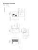
B. Dimensions / Connections Unit: mm (in.) 1.
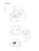
Unit: mm (in.) 2.
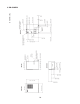
Unit: mm (in.) 3.
II. Installation and Operating Instructions WARNING 1. This icemaker must be installed in accordance with applicable national, state, and local regulations. 2. CHOKING HAZARD: Ensure all components, fasteners, and thumbscrews are securely in place after installation. Make sure that none have fallen into the storage bin. A. Checks Before Installation • Visually inspect the exterior of the shipping container and immediately report any damage to the carrier.
C. Location CAUTION 1. This icemaker is not intended for outdoor use. Normal operating ambient temperature should be within 45°F to 100°F (7°C to 38°C); Normal operating water temperature should be within 45°F to 90°F (7°C to 32°C). Operation of the icemaker, for extended periods, outside of these normal temperature ranges may affect icemaker performance. 2. This icemaker will not work at sub-freezing temperatures.
E. Electrical Connection WARNING For All Models 1. Electrical connection must be hard-wired and must meet national, state, and local electrical code requirements. Failure to meet these code requirements could result in death, electric shock, serious injury, fire, or extensive damage to equipment. 2. This unit requires an independent power supply. See the nameplate for proper voltage and breaker/fuse size.
F. Installation of Remote Condenser Unit WARNING 1. Installation of remote condenser unit must be performed by properly trained and EPA-certified service personnel. 2. Failure to install the equipment within these guidelines may adversely affect safety, performance, component life, and warranty coverage. 1. Checks Before Installation 1) Remove the shipping carton, tape, and packing material. 2) Check that the refrigerant lines do not rub or touch lines or other surfaces, and that the fan blade moves freely.
3. Setup 1) Secure the legs to the remote condenser unit with the 8 bolts and nuts provided. See Fig. 5. 2) The legs have 8 mounting holes. Secure the legs with 8 bolts (not included). Fig. 5 Bolts with Split Lock Washer and Flat Washer Nuts 4. Line Set CAUTION The icemaker, line set, and remote condenser unit must contain the same type of refrigerant. Mixing of refrigerants will result in improper operation and possible damage to the refrigeration system.
2) Connect the refrigerant lines to the appropriate male fittings on the remote condenser unit first and then at the icemaker. Make a proper connection as follows: a. Remove the protective covers from the male fitting and female coupling. b. Apply Polyol Ester (POE) refrigerant oil to the entire male fitting, including threads, o‑ring, and diaphragm, before making the connection. See Fig. 7. CAUTION Do not use thread sealant on the fittings. Use POE refrigerant oil only. c.
c. Make sure the male fitting and female coupling are properly aligned, then start the connection by hand to ensure that it is not cross threaded. d. Tighten the connection with a wrench until it is tight. At this point, the nut has covered most of the threads on the male fitting. e. Mark a reference line on the female coupling and the remote condenser unit or icemaker panel. Using a backup wrench on the back of the female coupling, tighten the six-sided nut of the female coupling an additional 1/6 turn.
5. Electrical Connection WARNING 1. Electrical connection must meet national, state, and local electrical code requirements. Failure to meet these code requirements could result in death, electric shock, serious injury, fire, or extensive damage to equipment. 2. THIS UNIT MUST BE GROUNDED. Be sure to install a proper ground from the icemaker to the remote condenser unit. Use wire of an appropriate gage and outdoor rating. Failure to properly ground this unit could result in death or serious injury. 3.
6. Stacking Remote Condenser Units 1) Install the lower remote condenser unit as described earlier in this section. 2) Place the upper remote condenser unit on top of the lower. See Fig. 10. 3) Secure the upper remote condenser unit to the lower remote condenser unit with the 4 screws provided. 4) Install refrigerant lines and make electrical connection as described earlier in this section. Upper Remote Condenser Unit Screws Screws Lower Remote Condenser Unit Fig.
G. Water Supply and Drain Connections See Fig. 11, 12, or 13 WARNING 1. Water supply and drain connections must be installed in accordance with applicable national, state, and local regulations. 2. Normal operating water temperature should be within 45°F to 90°F (7°C to 32°C). Operation of the icemaker, for extended periods, outside of this normal temperature range may affect icemaker performance. 3.
1. Icemaker • Icemaker water supply inlet is 1/2" female pipe thread (FPT). A minimum of 3/8" OD copper tubing is recommended for the icemaker water supply line. • An icemaker water supply line shut-off valve and drain valve should be installed. • Icemaker drain outlet is 3/4" FPT. A minimum of 3/4" OD hard pipe is recommended for the icemaker drain line. Condensation drain outlet is 3/8" OD stainless tube. The condensation drain line can be connected to the icemaker drain line or can be run separately.
2. Water-Cooled Condenser a) Connection to an Open Drain System • Condenser water supply inlet is 1/2" female pipe thread (FPT). A minimum of 3/8" OD copper tubing is recommended for the condenser water supply line. • A condenser water supply line shut-off valve and drain valve should be installed. • Condenser drain outlet is 3/8" FPT. A minimum of 3/8" OD hard pipe is recommended for the condenser drain line. • In some areas, a back flow preventer may be required in the cooling water circuit.
b) Connection to a Closed Loop System • Condenser water supply inlet is 1/2" female pipe thread (FPT). A minimum of 3/8" OD copper tubing is recommended for the condenser water supply line. • Condenser return outlet is 3/8" FPT. A minimum of 3/8" OD hard pipe is recommended for the condenser return line. • Shut-off valves and drain valves should be installed at both the condenser water supply inlet and condenser return outlet. • The water supply to the condenser should not drop below 4 GPM.
H. Final Checklist WARNING CHOKING HAZARD: Ensure all components, fasteners, and thumbscrews are securely in place after installation. Make sure that none have fallen into the storage bin.
I. Startup WARNING 1. All parts are factory-adjusted. Improper adjustments may adversely affect safety, performance, component life, and warranty coverage. 2. If the icemaker is turned off, wait for at least 3 minutes before restarting the icemaker to prevent damage to the compressor. 3. To prevent damage to the water pump seal, do not operate the icemaker with the control switch in the "WASH" position when the water tank is empty. 4.
III. Cleaning and Maintenance WARNING CHOKING HAZARD: Ensure all components, fasteners, and thumbscrews are securely in place after any cleaning or maintenance is done to the unit. Make sure that none have fallen into the storage bin. A. Cleaning and Sanitizing Instructions Hoshizaki recommends cleaning and sanitizing this unit at least once a year. More frequent cleaning and sanitizing, however, may be required in some existing water conditions. WARNING 1.
1. Cleaning Procedure 1) Dilute 16 fl. oz. (473 ml) of recommended cleaner Hoshizaki "Scale Away" or "LIME‑A‑WAY" (Economics Laboratory, Inc.) with 3 gal. ( 11 l) of warm water. 2) Remove all ice from the evaporator and the storage bin. Note: To remove cubes on the evaporator, turn off the power supply and turn it back on after 3 minutes. The harvest cycle starts and the cubes will be removed from the evaporator. 3) Turn off the power supply.
21) Move the control switch to the "WASH" position. 22) Replace the front panel in its correct position. 23) Turn on the power supply to rinse off the cleaning solution. 24) Turn off the power supply after 5 minutes. 25) Remove the front panel. 26) Disconnect one end of the pump tubing to drain the water tank. After the water tank has drained, reconnect the pump tubing. 27) Repeat steps 15 through 26 three more times to rinse thoroughly. Note: If you do not sanitize the icemaker, go to step 10 in "2.
B. Maintenance This icemaker must be maintained individually, referring to the instruction manual and labels provided with the icemaker. WARNING 1. Only qualified service technicians should attempt to service or maintain this icemaker. 2. Disconnect power before performing service or maintenance. 1. Stainless Steel Exterior To prevent corrosion, wipe the exterior occasionally with a clean, soft cloth. Use a damp cloth containing a neutral cleaner to wipe off oil or dirt buildup. 2.
C. Preparing the Icemaker for Long Storage CAUTION 1. When storing the icemaker for an extended time or in sub-freezing temperatures, follow the instructions below to prevent damage. 2. To prevent damage to the water pump seal, do not operate the icemaker with the control switch in the "WASH" position when the water tank is empty. When the icemaker is not used for two or three days under normal conditions, it is sufficient to move the control switch to the "OFF" position.
5) Open the water regulating valve by using a screwdriver to pry up on the spring retainer underneath the spring. While holding the valve open, blow out the condenser using the compressed air or carbon dioxide supply until water stops coming out. 6) Close the drain valve(s). 7) Replace the right side panel and front panel in their correct positions.
HOSHIZAKI AMERICA, INC. 618 Hwy. 74 S., Peachtree City, GA 30269 USA TEL (770) 487-2331 FAX (770) 487-3360 www.hoshizaki.