
Manual


Technical Data for Waterproof ReSet Call Point Series 01 & 11
Waterproof Series 01
Denotes a Waterproof ReSet Call Point that will interface with
most conventional fire alarm systems. It is fitted with two
internal 1 watt resistors 470 and 680 ohm. These are easily
accessed through the installer terminals as illustrated.
Waterproof Series 11
Denotes a Waterproof ReSet Call Point that incorporates two
independent single pole changeover switches providing double
pole changeover contacts. Easily accessed through installer
terminals as illustrated.
Current Rating (Series 01 & 11)
Current Rating (Series 11 only)
3 Amps 12 - 24V DC
3 Amps 125 - 250V AC
Housing and Mounting Box Material Polycarbonate
Electrical Contact Material Silver plated brass
Operating Temperature -20°C - +65°C
Installation Terminal Conductor Size 0.5mm - 2.5mm
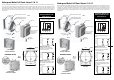
Waterproof ReSet Series 01 & 11
Specifications
Dimensions
NB: Switch arrangements shown with WRP ReSet in standby.
Mounting Method
1. Remove the Waterproof ReSet Call Point (WRP) from it’s
packaging. Detach the front cover from the backbox.
The earthing strap will be attached to the back box. You
have a choice to keep or remove the earthing strap.
2. Ensure the conduit or cabling lines up with the
conduit entries located on the top or bottom of the
back box and remove the desired conduit threaded
insert(s). It is recommended that entry to the WRP is
via the one or two 20mm threaded entries on the
bottom of the back box.
3. Take the back box (ensuring the two entries are located
at the bottom) and mark the position for the four fixing
screws.
4. Drill the holes and install the back box using the four
fixing screws and rawl plugs provided.
5. When the wiring connections are complete, fix the front
cover to the back box. There are x6 allen screws evenly
distributed around the front cover. Using the allen key
provided tighten each allen screw by one full turn, then
move onto the next. This will ensure that even pressure
is applied all the way around. See Dia C for
recommendation on the sequence to be used. The
recommended torque for the allen screws is 5 N•m.
In order to achieve IP67 rating, ensure the front cover is
securely tightened to the back box.
128mm
62mm
119mm
Front View
Side View
680
470
Accessories
STI F068 Allen Key
STI M210 WRP Test Key
STI F069 Earth Strap
STI C084 ‘O’ Ring
STI M227 20mm Threaded Insert
STI M228 Waterproof Washer
Technical Data for Waterproof ReSet Call Point Series 01 & 11
Waterproof Series 01
Denotes a Waterproof ReSet Call Point that will interface with
most conventional fire alarm systems. It is fitted with two
internal 1 watt resistors 470 and 680 ohm. These are easily
accessed through the installer terminals as illustrated.
Waterproof Series 11
Denotes a Waterproof ReSet Call Point that incorporates two
independent single pole changeover switches providing double
pole changeover contacts. Easily accessed through installer
terminals as illustrated.
Current Rating (Series 01 & 11)
Current Rating (Series 11 only)
3 Amps 12 - 24V DC
3 Amps 125 - 250V AC
Housing and Mounting Box Material Polycarbonate
Electrical Contact Material Silver plated brass
Operating Temperature -20°C - +65°C
Installation Terminal Conductor Size 0.5mm - 2.5mm
Waterproof ReSet Series 01 & 11
Specifications
Dimensions
NB: Switch arrangements shown with WRP ReSet in standby.
Mounting Method
1. Remove the Waterproof ReSet Call Point (WRP) from it’s
packaging. Detach the front cover from the backbox.
The earthing strap will be attached to the back box. You
have a choice to keep or remove the earthing strap.
2. Ensure the conduit or cabling lines up with the
conduit entries located on the top or bottom of the
back box and remove the desired conduit threaded
insert(s). It is recommended that entry to the WRP is
via the one or two 20mm threaded entries on the
bottom of the back box.
3. Take the back box (ensuring the two entries are located
at the bottom) and mark the position for the four fixing
screws.
4. Drill the holes and install the back box using the four
fixing screws and rawl plugs provided.
5. When the wiring connections are complete, fix the front
cover to the back box. There are x6 allen screws evenly
distributed around the front cover. Using the allen key
provided tighten each allen screw by one full turn, then
move onto the next. This will ensure that even pressure
is applied all the way around. See Dia C for
recommendation on the sequence to be used. The
recommended torque for the allen screws is 5 N•m.
In order to achieve IP67 rating, ensure the front cover is
securely tightened to the back box.
128mm
62mm
119mm
Front View
Side View
680
470
Accessories
STI F068 Allen Key
STI M210 WRP Test Key
STI F069 Earth Strap
STI C084 ‘O’ Ring
STI M227 20mm Threaded Insert
STI M228 Waterproof Washer