
Operation Manual


GB
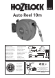
Contents
A
Auto Reel
B
Wall Bracket
C
Feeder Hose
D
Threaded Tap Connector
E
Hose End Connector
F
Waterstop Connector
G
Wall Plugs and Screws
H
Hose Nozzle
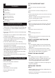
Quick hints and tips
obstructs the reel from swinging freely through 180°.
mount the reel.
spirit level.
turning on water supply.
distance (15 to 30cm) away from the reel and then
walked back towards the reel.
Turn off the tap and let the water out of the hose by
opening the hose nozzle/gun.
Walk back to the reel with the end of the hose and
trigger the rewind mechanism by taking hold of the
hose near to the reel, and gently pull the hose about
15 to 30cm to release the latch.
(Ensure that nothing is obstructing the hose whilst
the rewind procedure is active.)
when not in use.
TOOLS NEEDED:
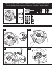
FIT THE WATER INLET HOSE
FIG.1
Remove the water connector as shown.
FIG.2
FIG.3
Fit the water connector to the end of the feeder hose
using the hose nut.
Take the 2 small screws and partially screw them
into the retaining clip as shown
Fit the retaining clip to the water connector.
FIG.4
water connector back into the reel and align the 2
screw holes.
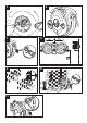
FIG.5
Screw the 2 screws into the reel
FIG.6
Fit the trim cap to the reel.
FIG.7
Attach the ‘water stop’ hose end connector to the
end of the main hose.
SELECT A SUITABLE POSITION FOR
INSTALLATION
FIG.8
The reel should be allowed to swivel through 180
degrees. Allow 40cm clearance on both sides of the
wall bracket.
the reel at least 1m from the corner and use a hose
guide, part No. 2392, which is not supplied.
FIXING THE WALL BRACKET
FIG.9
The 4 plugs and screws supplied are for use on
standard brick, concrete or timber walls only. To fix
the bracket to any other surface, you should use
screws and plugs appropriate for that surface.
A template is supplied, on the box, to help align the
screw hole positions.
INSTALLING THE REEL
FIG.10
Align the back of the reel with the wall bracket and
insert the grey pivot tube.
Attach the remaining hose end connector to the free
end of the feeder hose.