HP Modular Cooling System Maintenance and Service Guide Part Number 403349-003 October 2008 (Third Edition)
© Copyright 2006, 2008 Hewlett-Packard Development Company, L.P. The information contained herein is subject to change without notice. The only warranties for HP products and services are set forth in the express warranty statements accompanying such products and services. Nothing herein should be construed as constituting an additional warranty. HP shall not be liable for technical or editorial errors or omissions contained herein. Intended audience This guide is for an experienced service technician.
Contents Customer self repair ...................................................................................................................... 6 Parts only warranty service ......................................................................................................................... 6 Illustrated parts catalog ............................................................................................................... 17 Replaceable spare parts...........................................
Replacing the heat exchanger unit with couplers................................................................................ 63 Heat exchanger unit (HEX) with ball valve .................................................................................................. 67 Removing the heat exchanger unit with ball valves............................................................................. 68 Replacing the heat exchanger unit with ball valves.........................................................
Water quality.............................................................................................................................. 139 Condensation management .......................................................................................................... 139 Frost damage.............................................................................................................................. 139 Diagnostic tools .........................................................................
Customer self repair HP products are designed with many Customer Self Repair (CSR) parts to minimize repair time and allow for greater flexibility in performing defective parts replacement. If during the diagnosis period HP (or HP service providers or service partners) identifies that the repair can be accomplished by the use of a CSR part, HP will ship that part directly to you for replacement. There are two categories of CSR parts: • Mandatory—Parts for which customer self repair is mandatory.
• Obligatoire - Pièces pour lesquelles la réparation par le client est obligatoire. Si vous demandez à HP de remplacer ces pièces, les coûts de déplacement et main d'œuvre du service vous seront facturés. • Facultatif - Pièces pour lesquelles la réparation par le client est facultative. Ces pièces sont également conçues pour permettre au client d'effectuer lui-même la réparation.
NOTA: alcuni componenti HP non sono progettati per la riparazione da parte del cliente. Per rispettare la garanzia, HP richiede che queste parti siano sostituite da un centro di assistenza autorizzato. Tali parti sono identificate da un "No" nel Catalogo illustrato dei componenti. In base alla disponibilità e alla località geografica, le parti CSR vengono spedite con consegna entro il giorno lavorativo seguente.
anrufen und sich von einem Mitarbeiter per Telefon helfen lassen. Den Materialien, die mit einem CSRErsatzteil geliefert werden, können Sie entnehmen, ob das defekte Teil an HP zurückgeschickt werden muss. Wenn es erforderlich ist, das defekte Teil an HP zurückzuschicken, müssen Sie dies innerhalb eines vorgegebenen Zeitraums tun, in der Regel innerhalb von fünf (5) Geschäftstagen.
Centro de asistencia técnica de HP y recibirá ayuda telefónica por parte de un técnico. Con el envío de materiales para la sustitución de componentes CSR, HP especificará si los componentes defectuosos deberán devolverse a HP. En aquellos casos en los que sea necesario devolver algún componente a HP, deberá hacerlo en el periodo de tiempo especificado, normalmente cinco días laborables. Los componentes defectuosos deberán devolverse con toda la documentación relacionada y con el embalaje de envío.
periode, gewoonlijk vijf (5) werkdagen, retourneren aan HP. Het defecte onderdeel moet met de bijbehorende documentatie worden geretourneerd in het meegeleverde verpakkingsmateriaal. Als u het defecte onderdeel niet terugzendt, kan HP u voor het vervangende onderdeel kosten in rekening brengen. Bij reparatie door de klant betaalt HP alle verzendkosten voor het vervangende en geretourneerde onderdeel en kiest HP zelf welke koerier/transportonderneming hiervoor wordt gebruikt.
Serviço de garantia apenas para peças A garantia limitada da HP pode incluir um serviço de garantia apenas para peças. Segundo os termos do serviço de garantia apenas para peças, a HP fornece as peças de reposição sem cobrar nenhuma taxa. No caso desse serviço, a substituição de peças CSR é obrigatória. Se desejar que a HP substitua essas peças, serão cobradas as despesas de transporte e mão-de-obra do serviço.
Customer self repair 13
Customer self repair 14
Customer self repair 15
Customer self repair 16
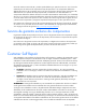
Illustrated parts catalog Replaceable spare parts The replaceable spare parts for the HP Modular Cooling System are listed in the following table.
Item Description Spare part number Customer self repair 4 SPS–TRANSFER SWITCH ("AC transfer switch" on page 26) 395773-001 Optional2 5 SPS–CONTROLLER, WATER ("Water group controller" on page 97) 395771-001 Optional2 6 SPS–SOLENOID, MAGNETIC VALVE ("Magnetic solenoid valve" on page 82) 399037-001 Optional2 7 SPS–CONDENSATE, PUMP & SENSORS ("Condensation pump and sensors" on page 47) 395775-001 Optional2 8 SPS–FAN, MAIN ("Fan unit" on page 50) 395777-001 Optional2 9 SPS–HARDWARE KIT, M
Mandatory: Obbligatorie—Parti che devono essere necessariamente riparate dal cliente. Se il cliente ne affida la riparazione ad HP, deve sostenere le spese di spedizione e di manodopera per il servizio. 2 Optional: Opzionali—Parti la cui riparazione da parte del cliente è facoltativa. Si tratta comunque di componenti progettati per questo scopo. Se tuttavia il cliente ne richiede la sostituzione ad HP, potrebbe dover sostenere spese addizionali a seconda del tipo di garanzia previsto per il prodotto.
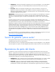
Flow meter repair There are two different flow meter types, depending on your MCS model. You should be able to discern which type you have, based on the label on the rear door of your MCS unit.
The Type 1 flow meter has a round body, and is no longer used in current MCS models. The Type 2 flow meter has a square body and ships installed in all current MCS models. There are two scenarios when repairing your flow meter: • You currently have a Type 1 flow meter that you will remove and replace with a Type 2 flow meter. For this type of repair, you will order the Miscellaneous Hardware Kit and have a trained technician complete your repair.
Removal and replacement procedures Removal and replacement procedure overview This section provides guidance for removing and replacing the HP Modular Cooling System (MCS) spare parts. Follow the instructions carefully to ensure proper installation of the new spare part. IMPORTANT: As you are removing the HP Modular Cooling System components, be sure to retain the screws in a safe place and separate them according to their type.
• • o T-25 Torx driver o Wire cutters Condensation pump and sensors o T-25 Torx driver o Phillips screwdriver Fan unit o • • • • • • T-25 Torx driver Flow meter paddle-wheel sensor o T-25 Torx driver o Wire cutters o Water hose fitting wrench (included with your original MCS unit) o Counter hold wrench (included with your original MCS unit) Heat exchanger unit (HEX) with coupler o T-25 Torx driver o Water hose fitting wrench (included with your original MCS unit) o Counter hol
o • 5-mm Allen wrench Water temperature sensor o T-25 Torx driver o Phillips screwdriver o (2) 18-mm wrench o Wire cutters Safety considerations Before performing service procedures, review the following safety information. Rack warnings and cautions Before installing a spare kit, be sure that you understand the following warnings and cautions.
WARNING: To reduce the risk of electric shock or damage to the equipment: • Do not disable the power cord grounding plug. The grounding plug is an important safety feature. • Plug the power cord into a grounded (earthed) electrical outlet that is easily accessible at all times. • Unplug the power cord from the power supply to disconnect power to the equipment. • Do not route the power cord where it can be walked on or pinched by items placed against it.
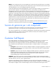
2. Confirm that no water is flowing into the MCS unit. AC transfer switch The AC transfer switch is located at the bottom front of the MCS unit. The following tools are required for installation: • T-25 Torx driver • Small Flathead screwdriver Removing the AC transfer switch 1. Power down the MCS unit ("Powering down the MCS unit" on page 24). 2. Open the front MCS door. 3. Slide the metal AC transfer switch box out toward you on the sliding rails.
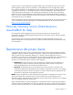
4. Using a T-25 Torx driver, remove the four Torx screws securing the AC transfer switch chassis to the water group controller chassis. The transfer switch chassis cannot be completely removed yet because the cables are still connected. 5. Disconnect the green and yellow ground bonding wires from the water group controller. 6. Disconnect the electrical power cables from the rear of the AC transfer switch.
a. Disconnect the three large cables, starting from the left and moving to the right, by inserting a small flathead screwdriver in between the cable connection and the latch, and pulling the cable out from the connector. b. Disconnect the three small cables, starting from the left and moving to the right, by pressing the small tab on the bottom of each small cable and pulling it out from the connector.
2. Connect the electrical power cables from the MCS unit to the AC transfer switch. a. Connect the three small cables, starting from the right and moving to the left, by pressing the tab on the bottom of each cable and pushing it into the connector.
b. Connect the three large cables, starting from the right and moving to the left, by pushing the cable into the connector. 3. Using a T-25 Torx driver, secure the AC transfer switch chassis to the water group controller chassis by inserting four Torx screws. CAUTION: To prevent damage to the cables and ensure proper fit of the transfer switch chassis, be sure to route all cables through the U-shaped opening in the rear of the chassis.
4. Slide the metal AC transfer switch box back into the MCS unit on the sliding rails. 5. Complete the operation checklist (on page 111). Air bleeder valve The air bleeder valve is located inside the MCS unit, centered at the top of the unit. The following tools are required for installation: • T-25 Torx driver • Pliers • Water hose fitting wrench (included with your original MCS unit) • Counter hold wrench (included with your original MCS unit) Removing the air bleeder valve 1.
4. Reach into the access panel cut-out. 5. Using a pair of pliers, unscrew the air bleeder valve from the check valve. 6. Remove the air bleeder valve from the MCS unit. To replace this component, see "Replacing the air bleeder valve (on page 32)." Replacing the air bleeder valve 1. Reach into the access panel cut-out and align the air bleeder valve to the check valve. 2. Firmly hand-tighten the air bleeder valve.
3. Slightly open the top vent of the air bleeder valve, approximately 3/4 turn, to allow for air flow. 4. Replace the top heat exchanger unit. ("Replacing the heat exchanger unit with couplers" on page 63) 5. Replace the top fan unit. ("Replacing the fan unit" on page 52) 6. Restore water flow to the MCS unit. ("Restoring water flow" on page 112) 7. Complete the operation checklist (on page 111). Air deflector plate The air deflector plate is not a spare part.
3. Lift the air deflector plate up, tilt it to an angle, and pull it out toward you. To replace this component, see "Replacing the air deflector plate (on page 34)." Replacing the air deflector plate 1. Reattach the ground bonding wires to the air deflector plate. 2. Align the two screw holes on the air deflector plate to the two screw holes inside the MCS unit. 3. Secure the air deflector plate to the MCS unit by tightening the two thumbscrews in the two screw holes.
No tools are required for this procedure. Removing the air sealing plate 1. Disconnect the condensation hose from the condensation pump by pressing in the plastic collar quick connect on the condensation pump. 2. Loosen the two thumbscrews securing the air sealing plate to the MCS unit.
3. Slide the air sealing plate out of the MCS unit. To replace this component, see "Replacing the air sealing plate (on page 36)." Replacing the air sealing plate 1. Slide the air sealing plate into the MCS unit.
2. Secure the air sealing plate to the MCS unit by tightening the two thumbscrews. 3. Connect the condensation hose to the condensation pump by inserting it into the plastic collar quick connect on the condensation pump.
Automatic door release The automatic door release kits are located on the front and rear doors of the rack attached to the MCS unit. The following tools are required for installation: • 3-mm Allen wrench • T-25 Torx driver • Wire cutters Removing the front automatic door release 1. Unplug the electromagnetic lock cable from the panel connector on the MCS unit.
2. Using an Allen wrench, remove the two black cap screws securing the electromagnetic lock to the electromagnetic lock bracket. 3. Remove the electromagnetic lock and cable from the rack. To replace this component, see "Replacing the front automatic door release (on page 39)." Replacing the front automatic door release 1. Align the electromagnetic lock to the electromagnetic lock bracket. 2.
3. Route the magnetic lock cable down through front extension channel, across the front of the rack, and plug it into the panel connector on the MCS unit.
Removing the rear automatic door release 1. Unplug the top and bottom electromagnetic lock cables from the extension lock cable. NOTE: Be sure to note the location of the electromagnetic brackets prior to removal.
2. Using a T-25 Torx driver, remove the four screws securing the upper and lower electromagnetic lock brackets to the rack chassis. 3. Using an Allen wrench, remove the two black cap screws securing each electromagnetic lock to its electromagnetic lock bracket. 4. Remove the electromagnetic locks and cables from the rack. To replace this component, see "Replacing the rear automatic door release (on page 42)." Replacing the rear automatic door release 1.
2. Using an Allen wrench, insert and tighten two black cap screws to secure each electromagnetic lock to its electromagnetic lock bracket. 3. Install the top electromagnetic lock bracket to the rack chassis in the location you noted during removal. a. Align the electromagnetic lock assembly to the rack chassis in the location you noted during removal. b. Using a T-25 Torx driver, insert and tighten two M5.
5. Route the magnetic lock cable through the rear extension channel, across the rack, and plug it into the panel connector on the MCS unit. Bottom fan unit The removal and replacement instructions for the bottom fan unit are provided so that you can access other components. If you are replacing the fan unit, see Fan unit (on page 50). No tools are required for this procedure. Removing the bottom fan unit 1. Open the rear MCS door. 2.
3. Loosen the two thumbscrews on the bottom of the fan unit. CAUTION: The fan unit weighs 16.8 kg (37 lb). Use extra caution when removing and replacing the top fan unit because it might be higher than your shoulders and is heavy and awkward to lift. 4. Pull the fan unit out toward you, and remove it from the MCS unit. To replace this component, see "Replacing the bottom fan unit (on page 45)." Replacing the bottom fan unit 1. Align the fan unit to the sliding rails. CAUTION: The fan unit weighs 16.
2. Slide the bottom fan unit inside the MCS unit on the sliding rails. 3. Tighten the two thumbscrews to secure the fan unit to the MCS frame.
4. Using a T-25 Torx driver, secure the horizontal shipping bracket to the MCS unit by inserting four Torx screws. Condensation pump and sensors The condensation pump and sensors are components of the water group located at the bottom interior of the MCS unit. The following tools are required for installation: • T-25 Torx driver • Phillips screwdriver Removing the condensation pump and sensors 1. Power down the MCS unit ("Powering down the MCS unit" on page 24). 2.
5. Disconnect the AC power cable from the condensation pump. 6. Disconnect the two sensor connections from the condensation pump.
7. Loosen the thumbscrew on the bottom of the condensation pump securing the condensation pump to the MCS unit (1), and lift the condensation pump from the MCS unit (2). To replace the component, see "Replacing the condensation pump and sensors (on page 49)." Replacing the condensation pump and sensors 1. Align the condensation pump thumbscrew to the hole inside the MCS unit (1), and tighten the thumbscrew on the bottom of the condensation pump to secure it to the MCS unit (2).
2. Connect the two sensor connectors to the condensation pump. 3. Connect the AC power cable to the condensation pump. 4. Replace the air sealing plate ("Replacing the air sealing plate" on page 36). 5. Relocate the power inlet box back into position ("Relocating the power inlet box back into position" on page 95). 6. Replace the bottom fan unit ("Replacing the bottom fan unit" on page 45). 7. Complete the operation checklist (on page 111).
You can replace the fan units during operation. The following tools are required for installation: • T-25 Torx driver Removing the fan unit 1. Open the rear MCS door. NOTE: The number of horizontal brackets varies depending on the position of the fan unit (top, middle, or bottom). 2. Using a T-25 Torx driver, remove the four Torx screws securing the horizontal shipping bracket to the MCS frame.
3. Loosen the two thumbscrews on the bottom of the fan unit. CAUTION: The fan unit weighs 16.8 kg (37 lb). Use extra caution when removing and replacing the top fan unit because it might be higher than your shoulders and is heavy and awkward to lift. 4. Pull the fan unit out toward you, and remove it from the MCS unit. To replace this component, see "Replacing the fan unit (on page 52)." Replacing the fan unit 1. Align the fan unit to the sliding rails. CAUTION: The fan unit weighs 16.8 kg (37 lb).
2. Slide the fan unit onto the sliding rails inside the MCS unit. 3. Tighten the two thumbscrews to secure the fan unit to the MCS frame. NOTE: The number of horizontal brackets varies depending on the position of the fan unit (top, middle, or bottom).
4. Using a T-25 Torx driver, secure the horizontal shipping bracket to the MCS unit by inserting four Torx screws. 5. Complete the operation checklist (on page 111). Flow meter sensor The flow meter sensor is a component of the water group located at the bottom interior of the MCS unit.
4. Relocate the power inlet box. ("Relocating the power inlet box" on page 93) 5. Remove the air sealing plate. ("Removing the air sealing plate" on page 35) 6. Remove the air deflector plate. ("Removing the air deflector plate" on page 33) 7. Remove the condensation pump and sensors. ("Removing the condensation pump and sensors" on page 47) 8. Remove the AC transfer switch. ("Removing the AC transfer switch" on page 26) 9. Remove the plastic lock washer from above the paddle-wheel sensor. 10.
12. Using the wire cutters, cut the cable connected to the paddle-wheel sensor and remove the sensor from the MCS unit. 13. Disconnect the paddle-wheel sensor cable connector, labeled X14, from the water group controller and pull the cable completely out of the MCS unit. To replace this component, see "Replacing the flow meter paddle-wheel sensor (on page 57).
Replacing the flow meter paddle-wheel sensor 1. Insert the keyed paddle-wheel sensor into the top of the flow meter. 2. Screw on the plastic screw cap to secure the paddle-wheel sensor to the flow meter.
3. Replace the plastic lock washer above the paddle-wheel sensor. 4. Route the paddle-wheel sensor cable through to the front of the MCS unit. 5. Connect the paddle-wheel sensor cable connector to the X14 connector on the water group controller. 6. Replace the AC transfer switch ("Replacing the AC transfer switch" on page 28). 7. Replace the condensation pump and sensors ("Replacing the condensation pump and sensors" on page 49). 8.
Heat exchanger unit (HEX) with coupler The three heat exchanger units are located on the front of the MCS unit. You can replace the HEX units during operation.
3. Disconnect the temperature sensor connector from the heat exchanger unit. 4. Using the counter hold wrench to hold the fitting in place and the water hose fitting wrench to loosen the water hose (both wrenches are included with your original MCS unit), disconnect the In and Out water hoses from the heat exchanger unit.
5. Disconnect the condensation hose from the heat exchanger unit. 6. Disconnect the green and yellow ground bonding wire grounding the heat exchanger unit to the MCS unit. 7. Open the front MCS door. IMPORTANT: Keep the Torx screws separated according to their thread type and note which thread type came from which hole location on the shipping bracket. 8. Remove the two heat exchanger unit shipping brackets. a.
c. Remove the heat exchanger unit shipping brackets from the MCS unit (3). CAUTION: The heat exchanger unit weighs 23.6 kg (52 lb) with the additional weight of the water. Use extra caution when removing and replacing the top heat exchanger unit because it might be higher than your shoulders and is heavy and awkward to lift.
9. Pull the heat exchanger unit out toward you. To replace this component, see "Replacing the heat exchanger unit ("Replacing the heat exchanger unit with couplers" on page 63)." Replacing the heat exchanger unit with couplers CAUTION: The heat exchanger unit weighs 23.6 kg (52 lb) with the additional weight of the water. Use extra caution when removing and replacing the top heat exchanger unit because it might be higher than your shoulders and is heavy and awkward to lift.
1. Insert the new heat exchanger unit into the same position as the heat exchanger unit you removed. IMPORTANT: Keep the Torx screws separated according to their thread type and note which thread type came from which hole location on the shipping bracket. 2. Install the two heat exchanger unit shipping brackets. a. Align the heat exchanger unit shipping brackets to the screw holes on the heat exchanger unit and the MCS frame (1). b.
c. 3. Using a T-25 Torx driver, secure the two shipping brackets to the MCS frame by inserting and tightening four Torx screws (3). Open the rear MCS door.
4. Connect the green and yellow ground bonding wire to the heat exchanger unit. 5. Connect the condensation hose to the heat exchanger unit.
6. Using the counter hold wrench to hold the fitting in place and the water hose fitting wrench to tighten the water hose (both wrenches are included with your original MCS unit), connect the In and Out water hoses to the heat exchanger unit. 7. Connect the temperature sensor connector to the heat exchanger unit. 8. Replace the air deflector plate ("Replacing the air deflector plate" on page 34). 9. Replace the fan unit ("Replacing the fan unit" on page 52).
You can replace the HEX units during operation. The following tools are required for installation: • T-25 Torx driver • Adjustable wrench or pipe wrench Removing the heat exchanger unit with ball valves NOTE: For this procedure, remove the fan unit seated directly behind the heat exchanger unit you will remove. 1. Remove the fan unit ("Removing the fan unit" on page 51). 2. Remove the air deflector plate ("Removing the air deflector plate" on page 33).
4. Disconnect the condensation hose from the HEX unit. 5. Disconnect the green and yellow ground bonding wire grounding the HEX unit to the MCS unit. 6. Close the two ball valves inside the HEX unit.
7. Close the two ball valves on the hose assemblies attached to the HEX unit. 8. Using and adjustable wrench or a pipe wrench, disconnect the two ball valve hose assemblies from the HEX unit. 9. Wipe up any excess water from the hoses. 10. Open the front MCS door. IMPORTANT: Keep the Torx screws separated according to their thread type and note which thread type came from which hole location on the shipping bracket. 11. Remove the two HEX unit shipping brackets. a.
c. Remove the HEX unit shipping brackets from the MCS unit (3). CAUTION: The heat exchanger unit weighs 23.6 kg (52 lb) with the additional weight of the water. Use extra caution when removing and replacing the top heat exchanger unit because it might be higher than your shoulders and is heavy and awkward to lift.
12. Pull the HEX unit out toward you. To replace this component, see "Replacing the heat exchanger unit with ball valves (on page 72)." Replacing the heat exchanger unit with ball valves CAUTION: The heat exchanger unit weighs 23.6 kg (52 lb) with the additional weight of the water. Use extra caution when removing and replacing the top heat exchanger unit because it might be higher than your shoulders and is heavy and awkward to lift.
1. Insert the new HEX unit into the same position as the HEX unit you removed. IMPORTANT: Keep the Torx screws separated according to their thread type and note which thread type came from which hole location on the shipping bracket. 2. Install the two HEX unit shipping brackets. a. Align the HEX unit shipping brackets to the screw holes on the HEX unit and the MCS frame (1). b.
c. 3. Using a T-25 Torx driver, secure the two HEX unit shipping brackets to the MCS frame by inserting and tightening four Torx screws (3). Open the rear MCS door.
4. Connect the green and yellow ground bonding wire to the HEX unit. 5. Connect the condensation hose to the HEX unit.
6. Using an adjustable wrench or a pipe wrench, connect the two ball valve hose assemblies to the HEX unit. 7. Connect the temperature sensor connector to the HEX unit. 8. Open the ball valves inside the HEX unit.
9. Open the ball valves on the hose assemblies. 10. Confirm that water is flowing through the ball valve couplers, by touching the couplers. The couplers should be cold. 11. Replace the hose insulation over the couplers. 12. Replace the air deflector plate ("Replacing the air deflector plate" on page 34). 13. Replace the fan unit ("Replacing the fan unit" on page 52). 14. Complete the operation checklist (on page 111).
Removing the HEX coupling 1. Shut off the water flowing into the MCS unit. ("Shutting off the water" on page 25) 2. Remove the corresponding fan unit. ("Removing the fan unit" on page 51) 3. Remove the corresponding air deflector plate. ("Removing the air deflector plate" on page 33) 4. Disconnect the temperature sensor cable from the heat exchanger unit. 5. Slide back the insulation on either the In or Out water hose. 6.
7. Using a flathead screwdriver, loosen the hose from the HEX coupling. 8. Using a utility knife, carefully trim approximately 0.64 cm (0.25 in) off the water hose.
9. Remove the HEX coupling from the water hose. To replace this component, see "Replacing the HEX coupling (on page 80)." Replacing the HEX coupling 1. Insert the HEX coupling into the water hose.
2. Using a flathead screwdriver, tighten the hose clamp. 3. Connect the HEX coupling to the heat exchanger unit. 4. Using the water hose fitting wrench and the counter hold wrench, reconnect the appropriate In or Out water hose to the heat exchanger unit. 5. Confirm that the HEX coupling is fully engaged between the heat exchanger bulkhead and the coupling nut.
6. Reconnect the temperature sensor cable to the heat exchanger unit. 7. Slide the insulation back in place on the In or Out water hose up against the coupling. 8. Replace the air deflector plate ("Replacing the air deflector plate" on page 34). 9. Replace the fan unit ("Replacing the fan unit" on page 52). 10. Restore water flow to the MCS unit ("Restoring water flow" on page 112). 11. Complete the operation checklist (on page 111).
2. Remove the bottom fan unit ("Removing the bottom fan unit" on page 44). 3. Remove the air deflector plate ("Removing the air deflector plate" on page 33). 4. Adjust the water hoses connected to the rear of the bottom heat exchanger unit and hold them out of the way to reach the magnetic solenoid on the valve. This process can be difficult.
Replacing the magnetic solenoid valve 1. Using a Phillips screwdriver, connect the electrical connector from the MCS unit to the magnetic solenoid by inserting and tightening one Phillips screw. 2. Adjust the water hoses connected to the rear of the bottom heat exchanger unit and hold them out of the way to reach the solenoid valve post. This process can be difficult.
Management module The management module is located on the inside of the front door of the MCS unit. No tools are required for this procedure. Removing the management module 1. Power down the MCS unit ("Powering down the MCS unit" on page 24). 2. Open the front MCS door. 3. Disconnect the electrical cables from the management module.
4. Slide the management module off of the mounting bracket, and remove it from the inside of the front MCS door. To replace this component, see "Replacing the management module (on page 86)." Replacing the management module 1. Slide the management module onto the mounting bracket until it locks in place. CAUTION: To avoid damage to the management module connectors, do not allow the cables to pull on the management module connectors.
2. Connect the electrical cables from the MCS unit to the management module. 3. Power on the management module. 4. Press and hold the C key for five seconds to confirm the configuration settings. 5. Complete the operation checklist (on page 111).
Operator display The operator display is located on the front door of the MCS unit. The following tools are required for installation: • 8-mm socket • Small Flathead screwdriver Removing the operator display 1. Power down the MCS unit ("Powering down the MCS unit" on page 24). 2. Open the front MCS door. 3. Using an 8 mm socket or wrench, remove the three nuts and external star washers securing the operator display rear cover to the back of the front MCS door. 4.
5. Disconnect the connector between the operator display and the display button. 6. Disconnect the connector from the management module (1), and pull the cable up through the cable management hose (2). 7. Squeeze the four release tabs on the top and bottom of the operator display (1), and push the operator display from the back to the front through the front MCS door (2). NOTE: Cables are removed for clarity.
8. Remove the display button by squeezing the two release tabs on the sides of the display button (1) and pushing the display button from the back to the front through the front MCS door (2). To replace this component, see "Replacing the operator display (on page 91).
Replacing the operator display 1. Hold the four release tabs while pushing the operator display from the front to the back through the front MCS door. 2. Hold the two release tabs while pushing the display button from the front to the back through the front MCS door.
3. Push the cable down through the cable management hose (1), and connect it to the management module connector (2). 4. Connect the connector between the operator display and display button. 5. Slide any extra slack in the cable lines up into the operator display rear cover, and secure by inserting the rubber grommet into the designated notch on the operator display rear cover.
6. Using an 8 mm socket or wrench, secure the operator display rear cover to the back of the operator display by inserting three nuts and external star washers. 7. Complete the operation checklist (on page 111). Power inlet box The power inlet box is not a spare part. The relocation instructions for the power inlet box are provided so that you can access other components. No tools are required for this procedure. Relocating the power inlet box 1.
b. Lift the right side of the bracket up at a slant, and pull the bracket out of the MCS unit (2). IMPORTANT: Do not disconnect any of the internal electrical connections to the power inlet box. 3. Pull the power inlet box toward you until it stops.
4. Set the power inlet box aside in the side cavity by lifting the right side of the power inlet box up until the box sits vertically on the left side of the MCS unit. To replace this component, see "Relocating the power inlet box back into position (on page 95)." Relocating the power inlet box back into position 1. Lower the right side of the power inlet box until it is back into the horizontal position.
2. Push the power inlet box back into the MCS unit until it locks in place. 3. Replace the outer support bracket. a. Lift the right side of the bracket up at a slant, and slide the bracket into the MCS unit. b. Tighten the four thumbscrews to secure the outer bracket to the MCS unit. 4. Connect the green and yellow ground bonding wire to ground the outer support bracket to the MCS unit.
Water group controller The water group controller is located at the bottom front of the MCS unit. The following tools are required for installation: • T-25 Torx driver • Flathead screwdriver • 8-mm socket Removing the water group controller 1. Power down the MCS unit ("Powering down the MCS unit" on page 24). 2. Remove the AC transfer switch ("Removing the AC transfer switch" on page 26). 3. Disconnect the seven electrical cables in the front of the water group controller.
4. Using an 8 mm socket, remove the two 8 mm nuts and washers securing the water group controller bracket to the water group controller chassis. 5. Disconnect the two large electrical cables from the back of the water group controller. 6. Disconnect the green and yellow grounding wire securing the water group controller to the water group controller chassis.
7. Remove the water group controller (mounted on a bracket) from the water group controller chassis. 8. Slide the water group controller off of the mounting bracket. To replace this component, see "Replacing the water group controller (on page 100).
Replacing the water group controller 1. Slide the water group controller onto the mounting bracket until it locks in place. 2. Connect the green and yellow grounding wire to secure the water group controller to the water group controller chassis. 3. Connect the two large electrical cables to the back of the water group controller.
4. Place the water group controller (mounted on the bracket) in the water group controller chassis. 5. Using an 8 mm socket, secure the water group controller bracket to the water group controller chassis by inserting two washers and two 8 mm nuts.
6. Connect the seven electrical cables to the front of the water group controller. 7. Replace the AC transfer switch ("Replacing the AC transfer switch" on page 28). 8. Complete the operation checklist (on page 111). Water inlet coupling The water inlet coupling is located on the inlet water hose connected to the MCS unit. The following tools are required for installation: • 5-mm Allen wrench Removing the water inlet coupling 1. Power down the MCS unit.
3. Using a pipe wrench, loosen the water inlet coupling and disconnect the water inlet hose from the supply hose. 4. Using an Allen wrench, remove the four Allen nuts and bolts securing the two brackets to the water inlet hose.
5. Remove the two brackets from around the water inlet hose. IMPORTANT: Water will drain out of the hose when you remove the coupling. Be prepared to catch excess water drainage in a bucket or floor drain. 6. Remove the water inlet coupling from the water inlet hose. To replace this component, see "Replacing the water inlet coupling (on page 105).
Replacing the water inlet coupling 1. Insert the water inlet coupling into the water inlet hose. 2. Align the two brackets around the water inlet hose. 3. Using an Allen wrench, insert and tighten three 40-mm Allen nuts and bolts into three of the four screw holes.
4. Using an Allen wrench, insert and tighten one of the original Allen nuts and bolts into the remaining screw hole. Compress completely. 5. One by one, replace the three 40-mm Allen nuts and bolts with the original Allen nuts and bolts, until the brackets are firmly compressed around the water inlet hose. 6. Using a pipe wrench, reconnect the water inlet hose to the supply hose and tighten the water inlet coupling. 7. Restore water flow to the MCS unit ("Restoring water flow" on page 112). 8.
Water temperature sensor The water temperature sensor is a component of the water group located at the bottom interior of the MCS unit. The following tools are required for installation: • T-25 Torx driver • Phillips screwdriver • (2) 18-mm wrench • Wire cutters Removing the water temperature sensor 1. Power down the MCS unit. ("Powering down the MCS unit" on page 24) 2. Shut off the water flowing into the MCS unit. ("Shutting off the water" on page 25) 3. Remove the bottom fan unit.
9. Using two 18-mm wrenches, loosen the cap nut from the water temperature sensor. 10. Using the wire cutters, cut the cable connected to the water temperature sensor, and remove the water temperature probe and cable from the MCS unit. 11. Disconnect the appropriate water temperature sensor cable connector from the water group controller and pull the cable completely out of the MCS unit. a. Disconnect the X12 cable connector if you are repairing the inlet water temperature sensor.
b. Disconnect the X13 cable connector if you are repairing the outlet water temperature sensor. To replace this component, see "Replacing the water temperature sensor." Replacing the water temperature sensor 1. Insert the new water temperature sensor probe into the appropriate water line. 2. Place the cap nut over the water temperature sensor.
3. Using two 18-mm wrenches, tighten the cap nut over the water temperature sensor. 4. Route the water temperature sensor cable through to the front of the MCS unit. 5. Connect the water temperature sensor cable connector to the water group controller connector labeled either X12 or X13. 6. Replace the AC transfer switch ("Replacing the AC transfer switch" on page 28). 7. Replace the condensation pump and sensors ("Replacing the condensation pump and sensors" on page 49). 8.
Operation checklist 1. If you disconnected the power, restore power to the MCS unit ("Restoring power to the MCS unit" on page 111). 2. If you shut off the water flowing into the MCS, restore water flow to the MCS unit ("Restoring water flow" on page 112). 3. Clear all old logs from the web interface to ensure that any additional alarms are current. 4. Confirm that no additional warning or alarm messages have been detected by looking at the operator display. Restoring power to the MCS unit 1.
3. Connect the two AC power cables to the power connectors on the power inlet box. 4. Open the front MCS door. 5. Turn on the AC1 breaker on the AC transfer switch. 6. Turn on the AC2 breaker on the AC transfer switch. Restoring water flow If water was disconnected, restore water flow to the MCS unit at the facility-side valve.
Technician repair removal and replacement procedures WARNING: You must follow the removal and replacement instructions listed in the site preparation guide, the user guide, and the maintenance and service guide. Failure to follow the instructions listed in these guides can void your warranty and service contract.
*Only the diaphragm and spring are shown, though the entire magnetic valve ships in the kit. **The removal and replacement instructions for this component are not included in this document.
NOTE: This procedure is specifically for the removal of the Type 1 flow meter. 1. Power down the MCS unit ("Powering down the MCS unit" on page 24). 2. Shut off the water flowing into the MCS unit ("Shutting off the water" on page 25). 3. Remove the bottom fan unit ("Removing the bottom fan unit" on page 44). 4. Relocate the power inlet box ("Relocating the power inlet box" on page 93). 5. Remove the condensation pump and sensors ("Removing the condensation pump and sensors" on page 47). 6.
10. Remove the flow meter from the water line. 11. Remove the two fiber gaskets on either side of the water line.
12. Disconnect the threaded pick-up at the top of the flow meter and pull the flow meter out of the MCS unit. 13. Remove the threaded pick-up and cable from the MCS unit, and disconnect from the connector labeled X14 on the water group controller. To replace this component, see "Replacing the flow meter (on page 117)." Replacing the flow meter NOTE: This procedure is specifically for the replacement of the Type 2 flow meter.
9. Replace the condensation pump and sensors ("Replacing the condensation pump and sensors" on page 49). 10. Relocate the power inlet box back into position ("Relocating the power inlet box back into position" on page 95). 11. Replace the bottom fan unit ("Replacing the bottom fan unit" on page 45). 12. Restore water flow to the MCS unit ("Restoring water flow" on page 112). 13. Complete the operation checklist (on page 111).
6. Using the counter hold wrench to hold the fitting in place and the water hose fitting wrench to loosen the water hose (both wrenches included with your original MCS unit), disconnect the In and Out water hoses from the bottom heat exchanger unit. 7. Remove the magnetic solenoid valve ("Removing the magnetic solenoid valve" on page 82). 8. Using an 8 mm Allen wrench, remove the four socket screws securing the cover of the magnetic valve.
9. Remove the cover from the magnetic valve. 10. Remove the diaphragm and spring from the magnetic valve. To replace this component, see "Replacing the magnetic valve diaphragm and spring (on page 120)." Replacing the magnetic valve diaphragm and spring NOTE: When you replace the diaphragm inside the magnetic valve, be sure to line up the tab of the diaphragm with the indentation of the magnetic valve. If it is not aligned properly, the cover will not fit correctly, which could cause further problems.
1. Place the diaphragm and spring on the magnetic valve. 2. Place the cover on the magnetic valve.
3. Using an 8 mm Allen wrench, secure the cover to the magnetic valve by inserting and tightening four socket screws. 4. Replace the magnetic solenoid valve ("Replacing the magnetic solenoid valve" on page 84). 5. Using the counter hold wrench to hold the fitting in place and the water hose fitting wrench to tighten the water hose (both wrenches included in your original hardware kit), connect the In and Out water hoses to the bottom heat exchanger unit. 6.
Upgrading procedures Viewing the upgrade procedures video Because of the difficulty of removing and replacing spare parts, HP recommends watching the HP Modular Cooling System Spare Replacement video. This video provides further explanation and detail of replacement strategies and techniques that might be helpful when attempting to remove and replace spare parts. You can access the video on the HP website (http://www.hp.com/go/mcs). 1. Select HP Modular Cooling System. 2.
5. Using a T-25 Torx driver, remove the three screws on each side of the bottom cover plate and remove the bottom cover plate from the HEX unit. 6. Using a flathead screwdriver, push in the tabs of the white electrical connector of the temperature sensor and push the connector into the HEX unit.
7. Using a flathead screwdriver, loosen the hose clamps attaching the condensation drain hose to the quick disconnect on the HEX unit face plate. NOTE: You might need to cut the condensation drain hose to remove it from the barbs. 8. Remove the condensation drain hose from both barbs. NOTE: Depending on the style of the hose barb, you might need to remove the hose barb before you remove the quick disconnect. If the hose barb is chrome-plated, remove it before you remove the quick disconnect. 9.
10. Using a small pipe wrench, loosen the nut attaching the HEX unit copper pipe to each of the ball valve assemblies. 11. Using a T-25 Torx driver, remove the four screws securing the coupler face plate to the HEX unit.
12. Remove the coupler faceplate and hose couplers as a single assembly. 13. Remove the O-ring from each pipe and verify that the pipe is clean. To replace this component, see "Replacing the HEX coupler (on page 128).
Replacing the HEX coupler 1. Install one O-ring on to each HEX unit pipe. 2. Install each ball valve assembly to the HEX unit tubing, positioning the handles down. 3. Loosely attach the HEX unit pipe nut to the ball valve assembly, barely connecting the threads.
4. Align the first faceplate (faceplate with eight side holes) to the ball valve assemblies, and slide the faceplate over the ball valve assemblies. 5. Align the second faceplate (faceplate with round holes) to the ball valve assemblies and slide the faceplate over the ball valve assemblies.
6. Using a T-25 Torx driver, install four screws to secure the faceplate. NOTE: Do not overtighten the fittings. The gasket needs only a slight compression to seal the fitting. 7. Using a small pipe wrench, tighten the fitting that connects the HEX unit copper pipe to the ball valve.
8. Using an adjustable wrench, insert the quick disconnect for the drain hose in to the HEX unit. TIP: Use a light lubrication spray to ease installation of the hose barbs and hose clamps to hold the condensation drain line in place while working. 9. Connect the condensation drain line between the quick disconnect hose barb and the HEX unit hose barb. 10. Insert the white electrical connector into the faceplate, and verify that the tabs have locked in place. 11.
12. Using a T-25 Torx driver, insert and tighten three screws on each side of the bottom cover plate. 13. Turn the HEX unit right-side up, so it is sitting on the bottom cover plate. 14. Replace the heat exchanger unit ("Replacing the heat exchanger unit with couplers" on page 63). 15. Replace the air deflector plate ("Replacing the air deflector plate" on page 34). 16. Replace the fan unit ("Replacing the fan unit" on page 52).
2. Insert the washer inside the hose union fitting of the hose assembly. 3. Hand-tighten the union fitting on the assembly, aligning the compression washer to the HEX unit. NOTE: Do not overtighten the fittings. The gasket needs only a slight compression to seal the fitting.
4. Using an adjustable wrench, tighten the union fitting 1/8 flat. 5. Insert the HEX unit in to the MCS unit.
6. Connect the right-side ball valve hose to the left-side MCS return hose. Connect the left-side ball valve hose to the right-side MCS return hose. The hoses create a criss-cross pattern. 7. Cut the hose attached to the old coupler the same length of the replacement hose, and insert the hose barb from the HEX unit into the hose. 8. Remove the old coupler from the MCS unit. 9. Transfer the hose insulation from the old hose assembly to the new ball valve hose assembly, attached to the HEX unit. 10.
11. Insert the barbed-end of the hose from the new ball valve assembly attached to the HEX unit into the hose you clamped in step 10. 12. Tighten the hose clamp. 13. Slide the insulation back over the hose and secure with tie wraps. 14. Repeat steps 7 through 13 for the other HEX unit hose. 15. Open the valves inside the HEX unit and on each hose assembly. 16. Install the two HEX unit shipping brackets. a.
c. 17. Using a T-25 Torx driver, insert and tighten four Torx screws to the MCS frame (3). Connect the green and yellow ground bonding wire to the HEX unit.
18. Connect the condensation hose to the HEX unit. 19. Connect the temperature sensor cable to the HEX unit. 20. Replace the air deflector plate ("Replacing the air deflector plate" on page 34). 21. Replace the fan unit ("Replacing the fan unit" on page 52). 22. Complete the operation checklist (on page 111).
Maintenance Maintenance and service For information on maintenance and service, refer to the HP website (http://www.hp.com). Air and water heat exchanger maintenance The air and water heat exchanger requires no maintenance. If particulates are present in the cooling water, a filter must be fitted. Check the functioning of the condensation drainage system regularly. Regularly perform visual inspections for leaks (annually).
Before storage or transportation at sub-zero temperatures, the water cycle must be drained completely using compressed air. Avoid setting the target temperature lower than is necessary because the danger of falling below the dew point increases as water temperature decreases (condensation buildup). Ensure that the enclosure is sealed on all sides, and in particular at the cable inlet (condensation formation).
Troubleshooting HP Modular Cooling System troubleshooting Issue Resolution The water flow is low or not flowing. For more information, see the "Temperature Control settings" section in the HP Modular Cooling System Web Interface User Guide located on the Documentation CD included with this product. The fan speed is too low.
Specifications MCS specifications Item Specification Voltage 208–240 VAC +/- 10%, 50–60 Hz Maximum Height (including the rack) 200 cm (78.7 in) Maximum Width (including the rack) 90.9 cm (35.8 in) maximum Maximum Depth (including the rack and rack handle) 127 cm (50 in) Maximum Shipping Height (on skid) 224.8 cm (88.5 in) Maximum Shipping Width (on skid) 122 cm (48 in) Maximum Shipping Depth (on skid) 177.8 cm (70 in) Maximum Depth with Rear Extension Kit installed 142.5 cm (56.
Thermal and air flow performance Maximum thermal and air flow performance parameters Specifications Air temperature—inlet to rack-mounted components 25ºC (68ºF) Chilled water temperature 7º–10°C (45º–50°F) Total rack-mounted component air flow 2,600 cfm or less at 0 or more pressure drop across the rack-mounted components Chilled water flow rate 21 gal/min Chilled water pressure differential at flow needed to meet thermal specifications 2.
Acronyms and abbreviations CSR Customer Self Repair HEX heat exchanger MCS modular cooling system SPS spare part Acronyms and abbreviations 144
Index A O AC transfer switch 26, 28 air bleeder valve 31, 32 air deflector plate 33, 34 air sealing plate 34, 35, 36 automatic door release 38, 39, 41, 42 operation checklist 111 operator display 88, 91 C condensation pump 47, 49 CSR (customer self repair) 6 customer self repair (CSR) 6 D diagnostic tools 140, 141 E environmental specifications 143 F fan unit 44, 45, 50, 51, 52 flow meter 114 flow meter sensor 54, 57 H HEX HEX HEX HEX HEX coupler 123 coupling 77, 78, 80 hose coupler 132 unit with b
replacing the front automatic door release 39 replacing the HEX coupling 80 Replacing the HEX unit with ball valve 72 Replacing the HEX unit with coupler 63 replacing the magnetic solenoid valve 84 replacing the magnetic valve diaphragm and spring 120 replacing the management module 86 replacing the operator display 91 replacing the rear automatic door release 42 replacing the water controller 100 replacing the water inlet coupling 105 replacing the water temperature sensor 109 required tools 22, 114 restor